Aero Tuft Tests
This page describes an aerodynamic tuft test to visualize the airflow around a Pro Master camper van. The test is done with two roof configurations: 1) A fairly bare roof with just a roof fan and a single PV panel mounted far aft and close to the roof, and 2) A roof with a full roof rack installed.
In a tuft test, short lengths of yarn are taped to the vehicle in a grid pattern. When the vehicle is moving, the yarn strands show the direction of the airflow, and also show whether the airflow is attached (flowing smoothly over the surface), or separated from the surface and flowing in rapidly changing random directions. Even though it is a simple and cheap technique, it is probably the best tool in the aero engineers toolbox to see how air is flowing over the vehicle and to detect areas of separation (which are usually sources of high drag).
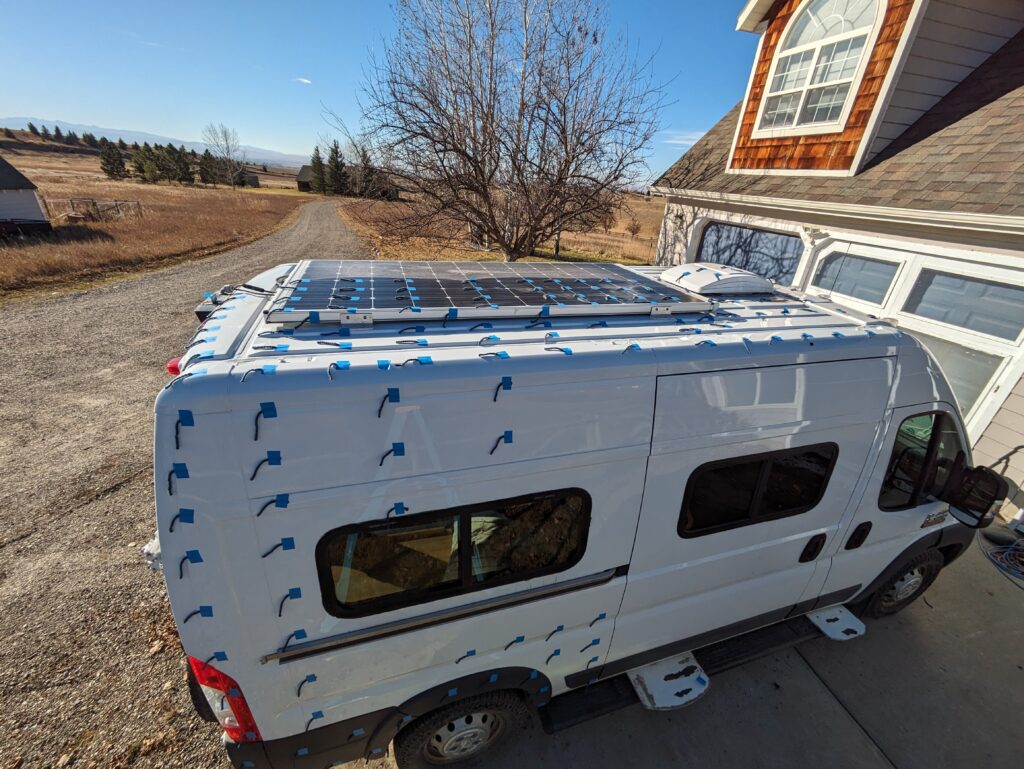
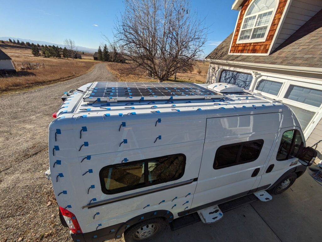
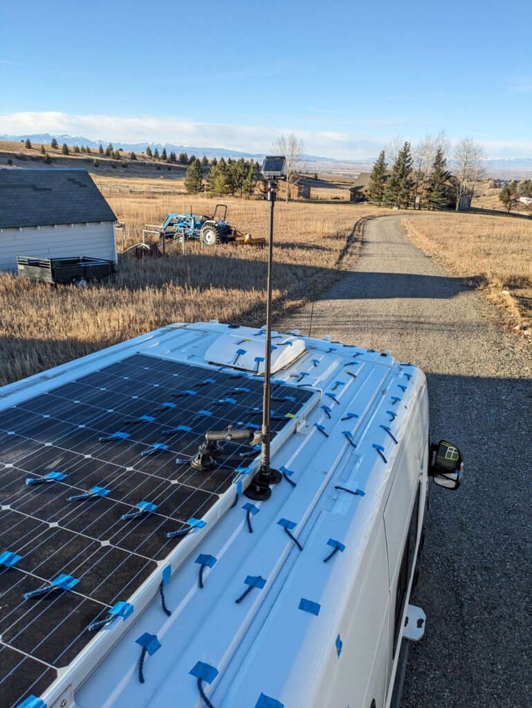
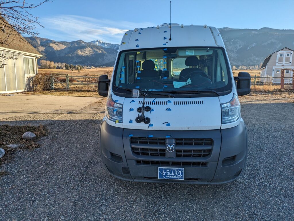
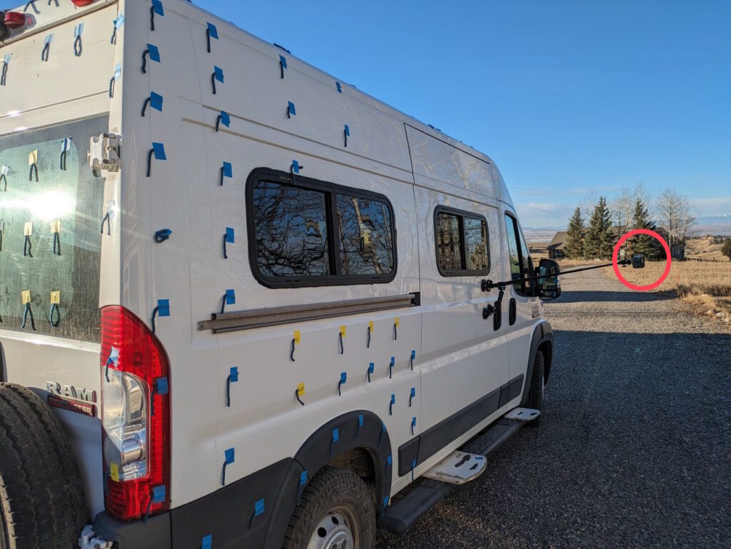
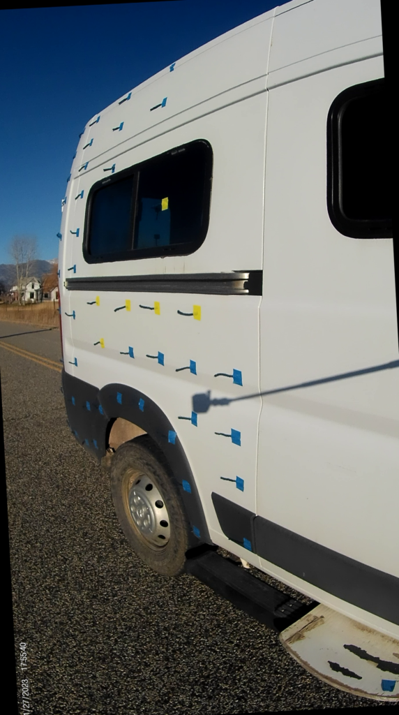
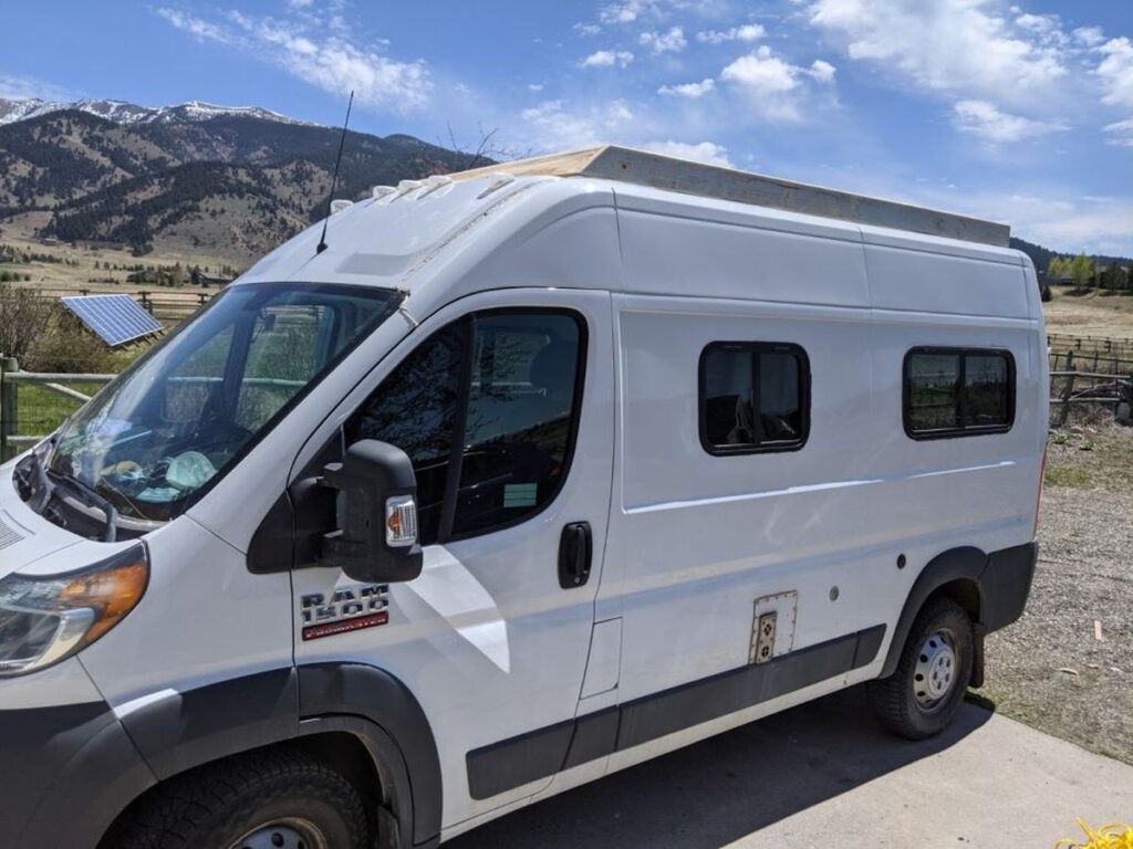
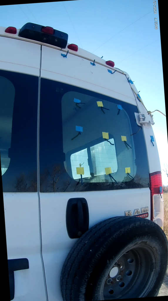
The van with tufts.
I taped yarn tufts to the roof, front, back and passenger side.
Test Setup
My tufts are wool yarn. Easy to make by wrapping several turns of yarn around a couple fingers and then cutting with scissors. Tufts about 3 inches long are good. The tuft color should contrast with the van color for good viability – the dark blue wool I used was fine over the white paint, but very poor over the dark grey trim areas. I taped the tufts to the van with regular painters tape, but then switched to waterproof painters tape after a few tufts came off. Don’t use any kind of tape that will leave a residue. The pattern of tufts is up to you – most people use a grid pattern, but it does not matter. The tufts should be close enough to give the detail you want to see in the flow pattern. I think my grid could be a bit tighter.
It took about two hours to apply the tufts to my van. I only did the passenger side of the van as it seems like the flow pattern would by symmetric, although in crosswinds this would not be true.
Its best to have all your test ducks in a row before you apply the tufts, as you want to be able to get the test done and be able to remove the tufts in a reasonable period of time.
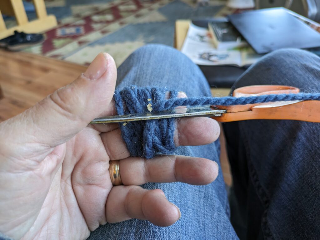
Wrap a few turns of yarn around two fingers, then cut with scissors.
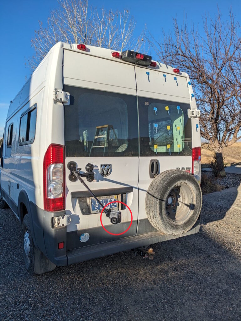
Probably the hardest part of tuft testing is to get a camera in a good position to see the tufts with the vehicle in motion. Some people have a friend drive the vehicle by and take pictures or videos from the side of the road. This is a bit tougher for a tall vehicle like a van. I got a camera mount that is able to mount to the van with magnets and suction cups and can stand the camera about 33 inches off the van. The camera I used is a GoPro like small camera. This worked pretty well, but you have to be careful not to hit anything with the camera sticking out. I took videos rather than still pictures, and I do think the videos provide more useful information.
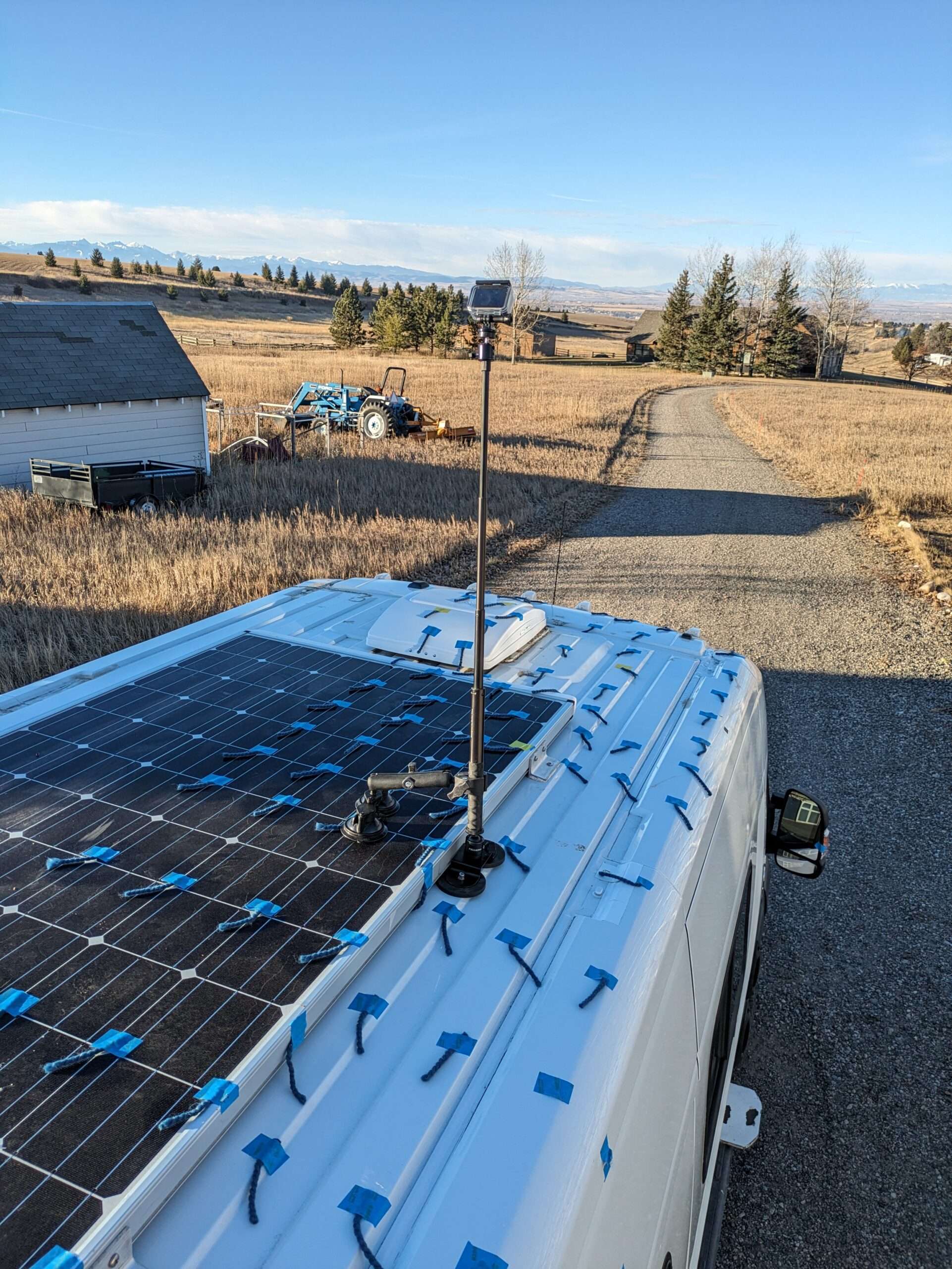
The GoPro like camera setup on the standoff mount. The mount is a PellKing that uses both suction cups and magnets to hold it in place. I used a safety tether just in case, but it never came loose during the testing.
I did have a problem on the first test attempt which was on a 20F day with the camera battery getting cooled by the 50 mph wind to the point where it died quickly. The next try was at 40F and with the camera in its diving case for insulation and the battery was fine. The final testing on both configurations was done on a calm wind, sunny day at 40F over an about two hour period.
Overall, I was impressed with how easy it is to do one of these tests and with the quality of the results. Getting useful aero data is not easy, but this simple method works well. It would be possible to tuft test a baseline area of a van and test an idea for improving it all in a single day.
Airflow Over the Base Van – No Roof Rack
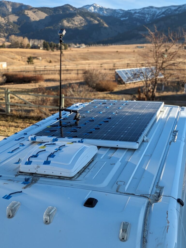
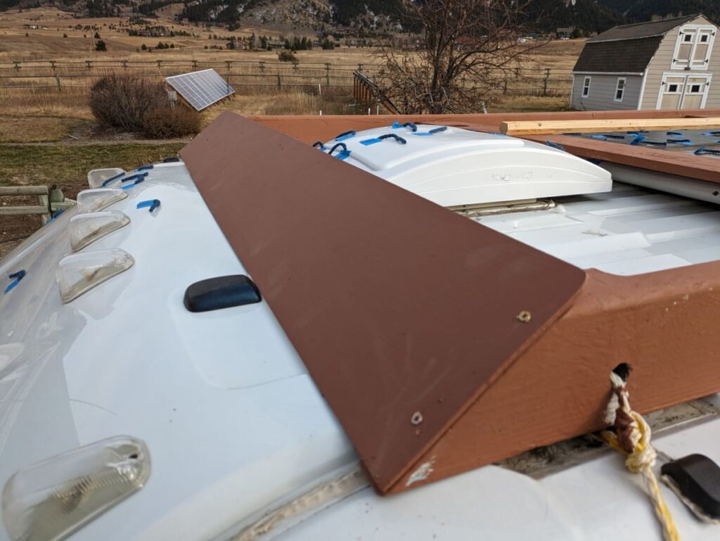
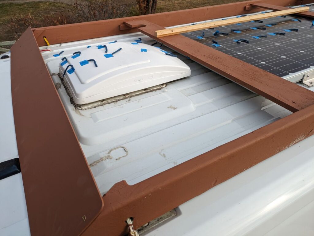
This first test was on my van as it is now. The roof has a Maxxfan mounted close to the front end of the roof, and has a single large PV panel (315 watts) mounted well aft on the roof. The PV panel is mounted as close to the roof as possible and as far aft as possible in an effort to reduce drag. The PV panel also has an elliptical nose fairing mounted on its front edge to reduce drag.
Flow On Forward Part of Roof:
The camera is positioned about half way back on roof looking forward. and down.
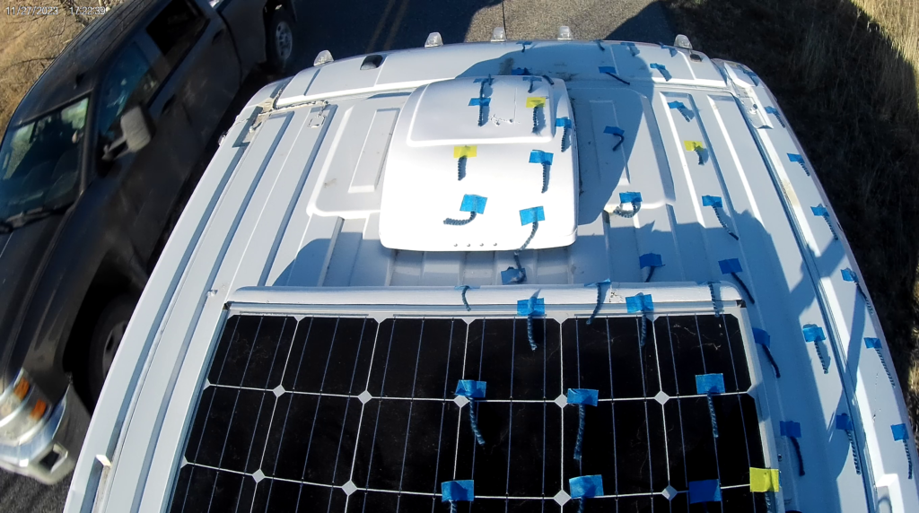
The flow looks to be attached and pointing aft except that the back surface of the Maxxfan has separated flow. Flow over the PV panel is attached and the elliptical nose fairing on the front of the PV panel appears to be doing its job in that the tufts on it and just aft of it indicate attached flow. The flow from the windshield onto the roof appears to be attached, so I guess the Fiat engineers got it right.
The tufts along the right edge of the roof indicate flow straight aft, so there is not much flow from the sides onto the roof or roof onto the sides.
Overall it looks pretty good to me. Any other thoughts?
Maybe its worth putting a boat-tail fairing on the back of the Maxxfan?
Flow On Aft Part of Roof:
The camera is positioned about half way back on roof and looking aft.
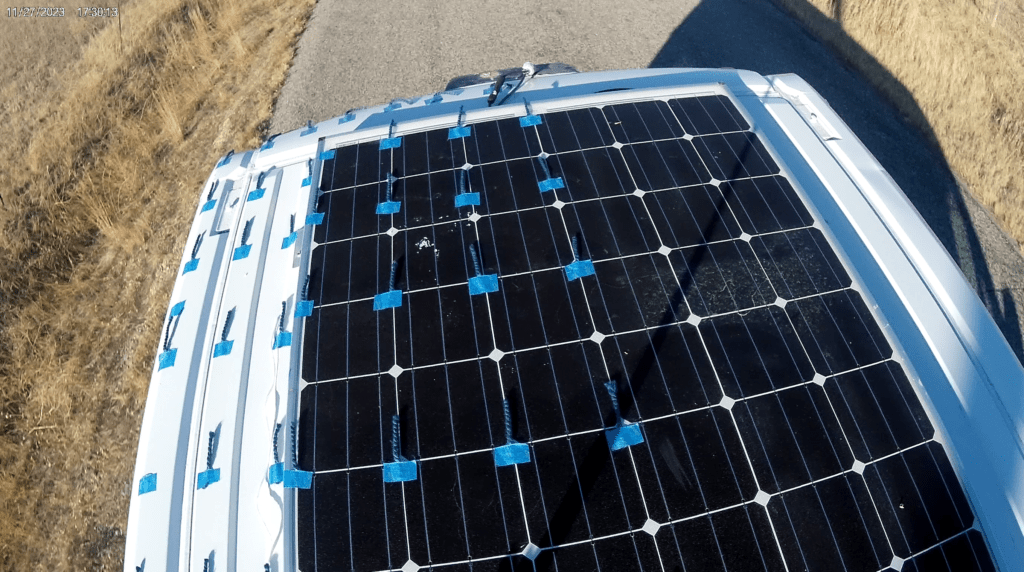
The flow appears to be directly aft and is attached over the PV panel and over the roof next to the PV panel.
Its hard to see the most aft tufts, but it looks like they are showing separation as would be expected on the back of the van.
Since the low pressure, separated area on the back of the van is likely the largest part of the van drag, I would like to look at could be done on the aft end of the roof and PV panel and sides to reduce the size of this separated wake area.
Flow On Front of Van:
The camera is positioned as shown, about 30 inches in front of hood.
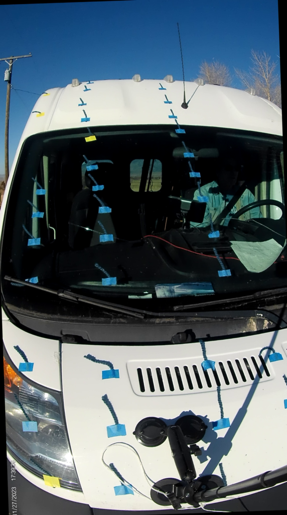
The flow appears to be attached with possible exception of the area around the windshield wipers . The flow up the center of the van tends to be straight back, where as the tufts toward the passenger side show a definite angle off to the side – apparently a significant amount of the flow goes around the side of the van. We tend to look at the side view wind tunnel pictures and tend to picture the flow as going over the top of the cars, but in fact a significant portion of the flow goes around the sides.
Flow On Back of Van:
While some of the tufts show a fair bit of random motion (indicating the expected separation on the back of the van), there does seem to be a generally downward flow pattern. It surprised me that the flow is this organized. It will be interesting to see what the static pressures in this area are.
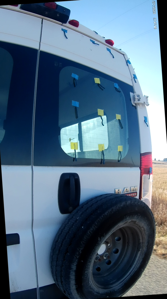
Flow On Side of Van:
I guess the first lesson is don’t use dark blue yarn tufts on dark grey parts of the van.
The flow looks to be moving uniformly aft and attached.
Airflow Over the Van with Roof Rack
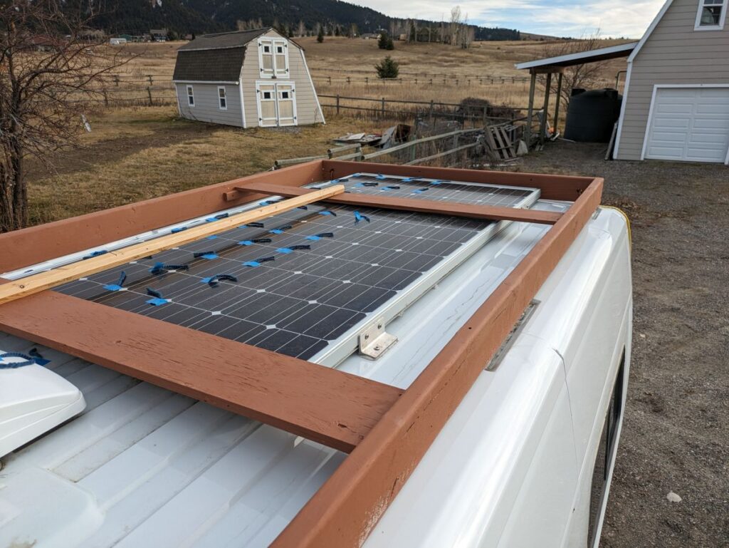
Sometime back, I got curious how much a full roof rack for a van cost in Miles Per Gallon. Just out of curiosity, I built a simulated full roof rack using scrap wood and did this pretty careful MPG test on it. It turns out that the full roof rack cost about 2.5 MPG. Since I was doing this tuft test and still had the simulated (wood) roof rack, I decided to put it on the van again and run the tuft test with it on to see how much different the airflow was with the roof rack compared to the base van — this is how that came out.
Some pictures of the simulated roof rack. The rack is the same as the one in the previous MPG test except that the front fairing board had somehow gone missing and this one is a new one.
Flow On Forward Part of Roof – with Roof Rack:
The camera position is the same as for the base van test (see above).
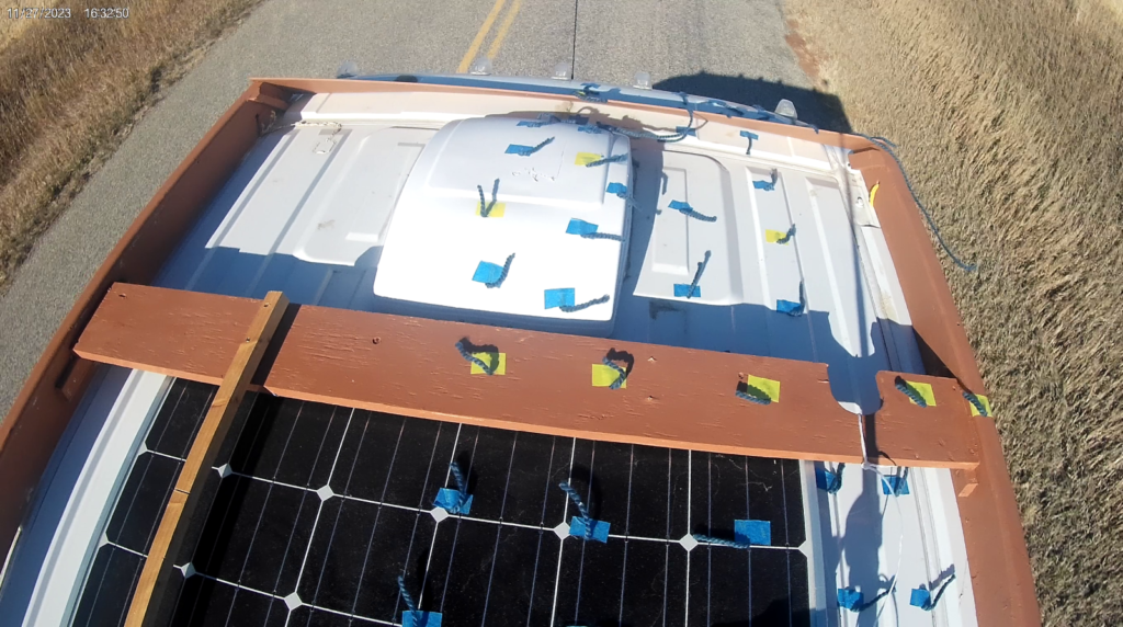
The flow pattern is completely changed from the pattern without the roof rack. The tufts show separated flow everywhere on the forward roof. In most areas the tufts indicate that the airflow direction is actually moving forward, not aft. The airflow coming over the forward “fairing” slab on the roof rack separates and does not reattach anywhere in the picture. The fairing slab will have high pressure on its upstream side due to the oncoming airstream and low pressure on the aft side due to the separation, so it will experience a high pressure drag force in addition to increasing the frontal area of the van. This is likely aggravated by fact that the air flow coming off the windshield and onto the roof is moving at a higher velocity due to the longer path length over the top of the van (like the flow over the top of a wing) and the drag force goes up with the square of velocity. I plan to measure the velocity and pressure levels in this area on a later test.
Flow On Aft Part of Roof – with Roof Rack:
This picture shows the tuft pattern for the aft half of the van roof with the roof rack in place.
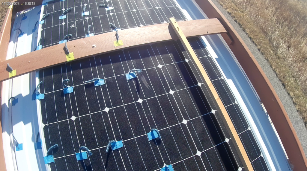
The picture shows that the separated flow that starts at the front end of the roof rack continues for the full length and width of the van roof – the flow never reattaches. It seems likely that separated airflow coming to the back of the van increases the size of the van wake, which is the largest source of drag on a blunt ended vehicle like a camper van.
Flow On Front of Van – with Roof Rack:
The tuft pattern over the front of the van looks identical for the base van and for the van with roof rack, so I have not provided a picture of the tufts for the front of the van with the roof rack.
Flow On Back of Van – with Roof Rack:
This picture shows the tuft pattern over the back of the van.
The tuft pattern on the back of van looks pretty similar with rack on or off.
It surprises me that there is not more vigorous movement of the tufts.
Further Planned Work
I am doing a video that will show short sections of the actual video for roof, front, back and side and with and without roof rack. I think the video shows the tuft patterns a little more clearly than the still pictures above.
I have pressure patches on the way that will allow measuring static pressures at various points on the van skin – this will likely be in the Spring as they are back ordered.
I plan to measure airflow velocities at a few key points on the van using Pitot tubes. I have most of the stuff to do this in hand.
Any thing else that could be measured that would be helpful?
I would like to look at some potential improvements to the van air flow.
- Close off the rear wheel wells with removable covers (like some of the 50’s cars had)
- Try a sort of boat tail fairing for the Maxxfan.
- Is there something that could be added to the PV panel that would reduce the size and depth of the low pressure, separated area that forms on the back of the van and is a major source of drag?
- Could something be added at the back of the van along the roof and along the end of the sides that would reduce the pressure drag on the back of the van? Maybe a short boat tail fairing, or something along the lines of the fold out Trailer Tails used on semi trucks, or ??
Thoughts on Roof Rack Design
My feeling is that between the roof rack MPG test and this test, there is pretty good evidence that this roof rack design with the full width “fairing” board at the forward end of the rack is not a good design – at least not from the aero drag and MPG points of view.
What might make a more efficient roof rack aero design? Here are some thoughts:
- Avoid using the “fairing” board at the front end of the rack. Its pretty clear that putting this big slab across at this critical point where high speed air is trying to make the turn from the windshield area onto the roof just results in total airflow separation that extends all the way to the back of the van.
- The fairing board also has a large frontal area and will very likely have a significant pressure difference across it due to the separated airflow behind – this means the fairing board itself adds a lot of drag. I do plan to measure the front and back pressure when my pressure patches arrive.
- I believe that it would be best for any structural rack members that have to cross the width of of the van should have as little frontal area as possible and should be a good low drag shape (like the Whisper Bar) – this should also reduce rack noise.
- I believe it would be better to move the front of the rack as far aft as possible. Placing objects in the critical area where the high speed flow is trying to make the turn from the windshield onto the roof seems like a bad idea.
- Even though the rack members that run forward and aft do not add much frontal area, and don’t generate a log of drag when the flow is from straight ahead, they will have more impact when there are cross winds and the net flow is at an angle to the van travel direction. So, using as small a members as possible with a good aero shape might pay good dividends.
- It seems like there might be an opportunity at the aft end of the rack to try to shape the flow to reduce the size of the separated, low pressure area behind the van that is likely the largest drag producer on the van.
These are my thoughts – what are your thoughts?
It seems like there is a lot of room for improvement with large savings in fuel costs and large reductions in CO2 emissions. I’d be happy to work with anyone who wants to work on this and to test the end product as best I can.
Where did you get the small, white fairing to mate to your solar panel? I’d like to bookmark it for future reference in my build. Many thanks!
Hi Bryce,
The fairing is made from a solid piece of wood with as table saw and planner.
I should have put a page up on it – will try to do that.
Its elliptical in shape as near as I could get it.
It does appear to result in smooth flow over the nose of the panel on this test …
No idea how much benefit it provides, but there are some tests out there on car roof racks (eg the Whisper Rack) where a good shape shows a good benefit.
Gary
Hi,
I added a few pictures of the fairing to the solar panel page…
If one were to install a large roof rack like that, I think installing some thin paneling that is level with the top of the front fairing of the roof rack, and the installed solar panels might help keep the airflow uninterrupted and an uninterrupted space.
Hi Bryce,
That would be a configuration that would be interesting to test, but I’m very skeptical that it would do significantly better than what I tested.
The “fairing” at the front of the rack adds a significant amount of frontal area and that will still be there.
In my test, the airflow separates at the fairing and does not reattach anywhere on the roof – this makes for a high drag coefficient. I think you would still get full separation at the aft edge of the fairing with the configuration you suggest – its a sharp edge in an area of critical high speed curving flow. With the smoother top surface, you might get reattachment of the airflow further back (or not). In either case, I don’t think its going to be pretty, but aero is hard and I can’t say for sure.
I think some of the thoughts on a lower drag solution discussed above have a better chance. But, aero is hard to predict 🙂
edit: if the fairing at the front of the rack were redesigned to have the same shape as the forward end of the PM roof and there was a smooth surface to transition onto behind the fairing, then I think you might not degrade the drage coefficient of the base PM, but there would still be the frontal area increase. I think thats the best you could do with the concept you sugggest, but it would take some grade A skills designing and making curved panels for the fairing.
Gary
Yeah I agree, the full frontal fairing is hard to overcome with the added frontal area and then needing to be a pretty good craftsman to smooth that transition out as best as possible.
Interesting. My first thought of aero was around the rearview mirrors and secondly the wipers. I’m going to play with a flexible aero shield for the mirrors so you can still open the doors. The rest of my van is unencumbered with roof racks or other. Good post, thanks.
Hi Phil,
Please let us know how the mirror experiment comes out.
This is an interesting video of the Tesla Cybertruck in the A2 wind tunnel.
One of the runs they did was without side view mirrors. They did not see a ton of difference, but the Cybertruck mirrors probably got a lot of attention from Tesla.
Gary
Very interesting stuff Gary! So great to see someone with a van that cares about carbon emissions! Thanks for all the work!
Thanks!
Awesome work. The van community owes you.