Introduction
This section covers adding a 1500 watt pure sine wave inverter to the basic electrical system.
This will allow you to use 120 VAC home appliances, even when you don’t have shore power to plug into – as long as they don’t exceed the 1500 watt capacity.
The electrical system flavors described on this site include this one that has a standalone inverter and can be paired (if desired) with separate shore power charger, OR a version in which the inverter and shore power charger are combined in a single unit. You want to pick one of these (not both!) – this page gives some of the pros and cons of each.
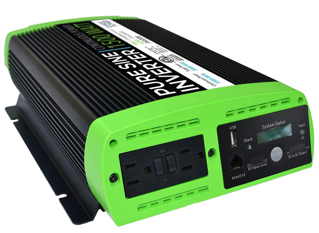
I chose this GoWise inverter because I think it is a good value. Its not a high end brand like Victron or Samlex, but it gets good reviews, and it has a US support contingent. The testing I did on it, which included running it right at the top end of its wattage range for significant periods, using it to run sensitive devices like microwaves, and running it with high loads at low supply voltage all turned out very good. If you have negative experience with this inverter, please let me know. There are, of course, many other inverters out there to choose from, so lots of alternatives if you don’t like green:)
One thing I should mention is that if you use this inverter to power large loads (eg a small microwave) with the two golf cart batteries, you are living near the maximum capability of the golf cart batteries. You should start with fully charged batteries, and you may find that for extended runs that you have to run the van engine at the same time. The two LiFePo4 batteries run these kinds of loads with more margin.
Wiring Diagram
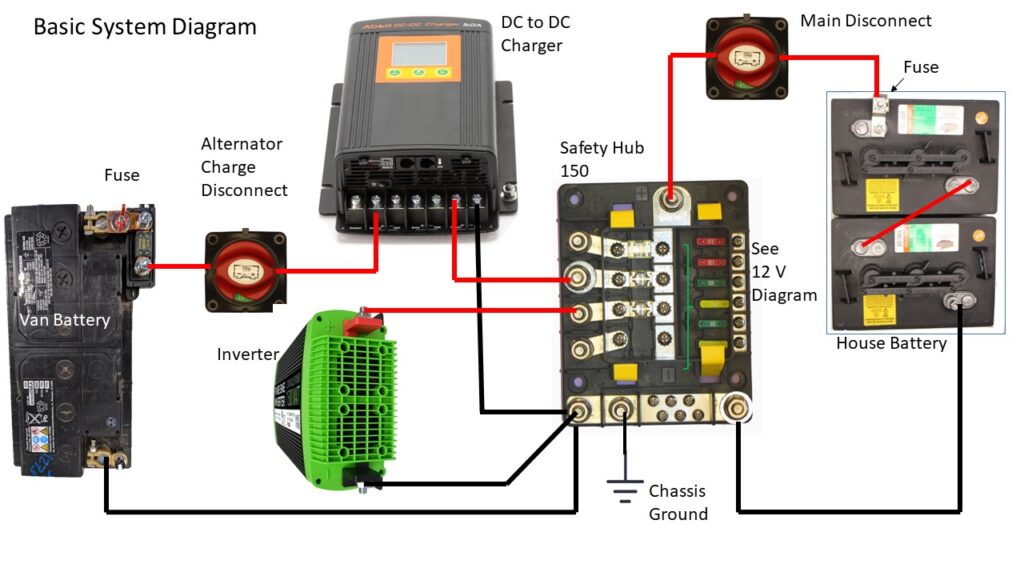
This is the Base System wiring diagram with the inverter added – its green!
Wiring
There are only three wires to hookup 🙂
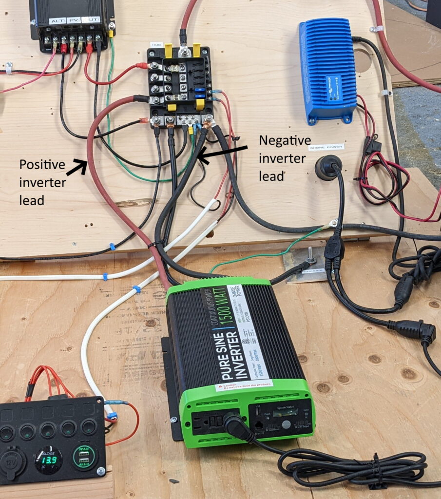
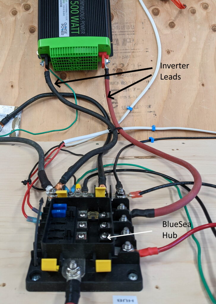
Connect an AWG #2 cable from the positive (red) terminal of the inverter to one of the 4 high amperage fused terminals on the Hub. This cable has 5/16 th inch (or M8) lugs on both ends. If you have a torque wrench, use 180 in-lb. The fuse at this position on the Hub should be a 200 amp AMI fuse (don’t forget to have a spare).
Connect the negative (black) cable of the same size in the same way as the positive lead. Any of the larger negative terminals on the Hub can be used.
Try to keep these supply lines from the Hub to the inverter as short as possible – the longer they are, the larger the voltage drop in these very high current wires.
Connect a wire from the grounding lug on the inverter either to one of the negative lugs on the Hub, or to a carefully prepared chassis ground. Use the same size wire as you use to supply the inverter for this ground wire – note that the one shown in the picture is too small and has been replaced.
Use the pictures for guidance, and leave a comment if you have a problem or question.
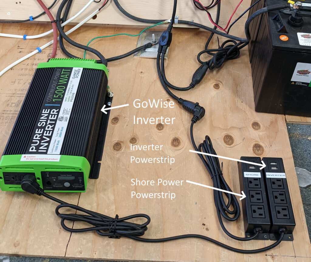
As the picture above shows, the AC side wiring for our system is no wiring – all you do is plug cords in. To keep things simple, separate power strips are used when on inverter power and when on shore power. When on inverter power, you plug into one strip, and when on shore power plug into the other strip. There is no AC distribution panel and no AC circuit breakers (except inside the inverter) and I don’t have AC outlets spread out all over the van. I had all these on the first version of the van and, in truth, they were a total waste of time an money. The only outlet we ever used was the one by the galley. So, this time we simplified it down to what we actually use, and the result was no wiring to do. Just plug one power strip into the inverter outlet and another into the shore power outlet. The van only has 60 sqft of floor area – one outlet is fine for us.
They do sell transfer switches that will change over from getting AC power from your inverter or from shore power automatically. But, just using the two plug strips is satisfyingly simple to me.
If you decide to DIY one of these transfer switches, be sure to read up on how they work. At the same time you switch from shore power to inverter power, the point at which the neutral is bonded the ground must be changed – if you are not sure what this means, then don’t DIY it until you do.
Battery Imposed Limits
For two golf cart batteries that are charged and in descent condition, I believe an inverter output wattage of about 1150 watts is sustainable. This is enough to run a so called 700 watt microwave (700 watt microwaves actually use about 1100 watts – the 700 watts is “cooking power”). This corresponds to about 120 amps input to the inverter with the voltage dropping down just below 12 volt. I would like to hear what other peoples actual experience has been.
For the two SOK batteries, the usable output is higher. My testing indicates it will run the 1500 watt GoWise inverter at full power sustainably, and with less battery voltage drop than the golf cart batteries. The SOK battery spec indicates it would run inverters up to about 2000 watts, but I would try to keep it to somewhat less than this.
So, this is one area that favors the SOK LiFePo4 batteries. If you want to run sustained higher wattage inverter loads you will be better off with the Li batteries.
Larger Inverters
The Bluesea Safety Hub 150 can handle inverters up to about 1800 watts hooked directly to it as we show for the GoWise above. Inverters larger than this cannot be hooked to the Hub and should be handled like this…
Please let me know in the comments if see any errors or misleading info here, or if more info should be added, or if you had any problems.
Gary 7/16/22
Hello there I love all of this information. It is excellent as I am going to install all this into my son’s small little RV trailer. I have a question for you. TomMake this work for me to convert all this camper van information into truck and trailer application. Does the seven pin connecter just go in line of the charging wire coming from the van battery? Or without getting too detailed or taking up too much of your time could you tell me how I can convert all of your diagrams into having this work for a small RV trailer? Everything makes sense it’s just hook up at the trailer ,the seven pin connector. Powerlead wire from the van to the dc to dc charger
Thanks so much!
Hi Jason,
So, it sounds like you want to have the house battery, DC to DC charger and the rest of trailer electrical system back on the trailer, but you want to be able to charge the house (trailer) battery from the tow vehicle alternator/battery?
The 7 pin trailer connector does have pins for +12 volts and for the ground return, but I don’t think you could use it for charging the trailer/house battery because the wire gauge would be too small.
I think you will probably need a separate higher capacity connector for the house battery charging.
Can you let me know the size of the DC to DC charger you plan to use, and how long the wire run will be from the tow vehicle battery back to the DC to DC charger? From this I can tell what wire gauge should be used.
Gary
Thanks for the reply ! I have a 40a dc charger truck length is approx 20-25ft .
Cheers !
Hi Jason,
I had a go at sizing the wire you need using the BlueSea Circuit Wizard.
I assumed 45 amps from the tow vehicle battery/alternator to the DC to DC – this should be a bit more than the rated output of the DC to DC as its not 100% efficient.
With such a long run back to the trialer, it takes pretty big wire to not have too much voltage drop along the wire. I used 5% voltage drop.
And, used 22 ft for the length of the run.
The Circuit Wizard comes up with #4 wire. The reason for the heavy gauge is to keep the voltage drop down. #10 wire would handle the current OK, but the voltage drop would be about 18%, so if the tow vehicle voltage was 13 volts, the voltage that gets to the DC to DC would only be about 10.6 volts and the DC to DC might not run on this.
If you used #6 wire, the voltage drop would be about 10% and with 13 volts from the tow vehicle, the voltage at the DC to DC with 45 amps in would be about 11.7 volts. You could look at the DC to DC specs and see if it would run on this or not.
Some DC to DC chargers also let you limit the max current, and if so, you could cut back on the 40 amps to maybe 30 amps and this would help reduce the voltage drop.
In any case, you don’t want to try to run this much current through the 7 pin connector. You will need a separate connector and it should be rated for 50 amps or so.
You will also want a fuse in the plus lead of this wire that is installed as close as possible to the tow vehicle battery. This protects against a short circuit of this wire to the chassis along its run.
You can play around with wire gauges, wire lengths and currents using the BlueSea Circuit Wizard.
Gary
excellent information, worthy of re-reading, based on just finishing building a similar system. Tried to use breakers instead of disconnects, the small red breakers are cheap, but they seem to trip at well below rated current. Yellow ones ok. Otherwise works great. Safetyhub is solid, worth it.
Nowadays the prebuilt power stations can do most of this and are getting very good, if the DCDC charging was better they would be a clear winner. This DIY is still much better for expanding the system.