There is has been an interesting discussion on the ProMaster forum on using a window air conditioning unit to cool camper van conversions. These window AC units are compact, cheap and fairly efficient, so they could be a good solution for cooling camper vans which are typically less than 100 sqft.
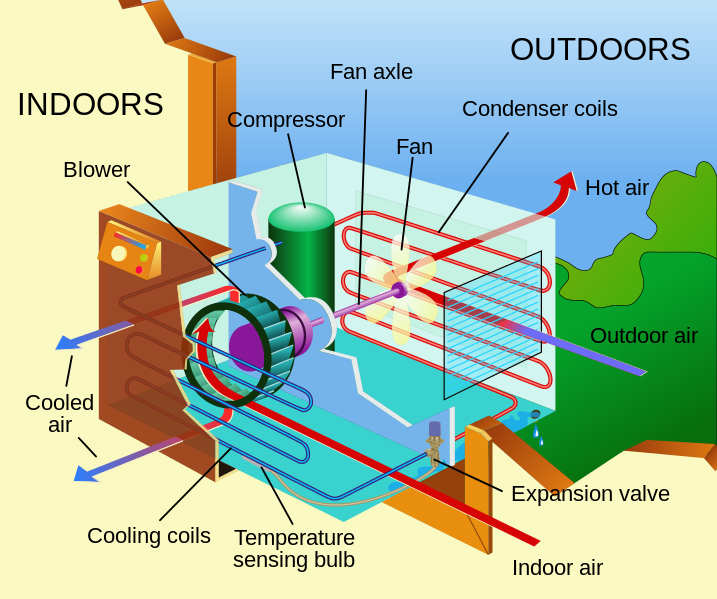
One way to install one of these units in a camper van is with the AC unit fully inside the van (say under a bed platform). Normally these units are installed in a window, and the condenser coil on the AC is outside and a condenser cooling fan picks up outside air from vents in the sides of the unit, forces this air through the condenser heat exchanger, and exhaust it out the back. If the unit is installed inside the van, then provisions must be made for cooling air for the condenser coil. Most of these installs use inlet ducts that go through the floor to supply the intake for condenser cooling air, and the condenser outlet vent can either be a rectangular vent cut in the side of the van, or more holes through the floor.

Its unclear how much these floor and sidewall vents impact the performance of the window AC unit.
Quick bottom line:
Its clear from the table below that the degradation in AC performance as you restrict the condenser cooling area can be severe — all the way up to having the AC shut down.
As you restrict condenser cooling air, the condenser temperature goes up, the cooling provided goes down, and the power consumption goes up quite a bit. If you are trying to get to an AC that will run off batteries, the added power consumption would be a problem.
On this 10K BTU AC, the configuration with four 4 inch condenser inlet ducts and no restrictions at all on the exhaust still increased condenser temperature by 10%, increased power consumption by 9%, and reduced cooling by 2%.
Going to a configuration with two 4 inch inlet ducts and two 4 inch outlet ducts increased condenser temperature by 43%, increased power consumption by 54%, and decreased cooling by 15%. This would effectively make an EER 10 AC into an EER 5.5. This seems pretty dismal to me, and the AC may not even be willing to operate for long periods under these conditions.
It seems like one approach that could be workable would be to place a louver vent panel in the side of the van that is about the same size as the AC’s heat exchanger (16 by 11 inches on this AC) to serve as the AC exhaust vent, and then use as much duct area through the floor as you can get in for the condenser intake.
Update: Added a test (bottom of this page) using a fan to force air through the condenser heat exchanger. This works quite well — the performance is essentially the same as the bare AC. See test below.
Update August 2018: Santiago has done some further testing with a 6000 BTU/hr window AC and come up with some good data. See this page for his design, prototype and testing…
His design completely packages the window AC unit within the van. The outside air to cool the window AC unit is brought up through openings int he floor.
Test Setup:
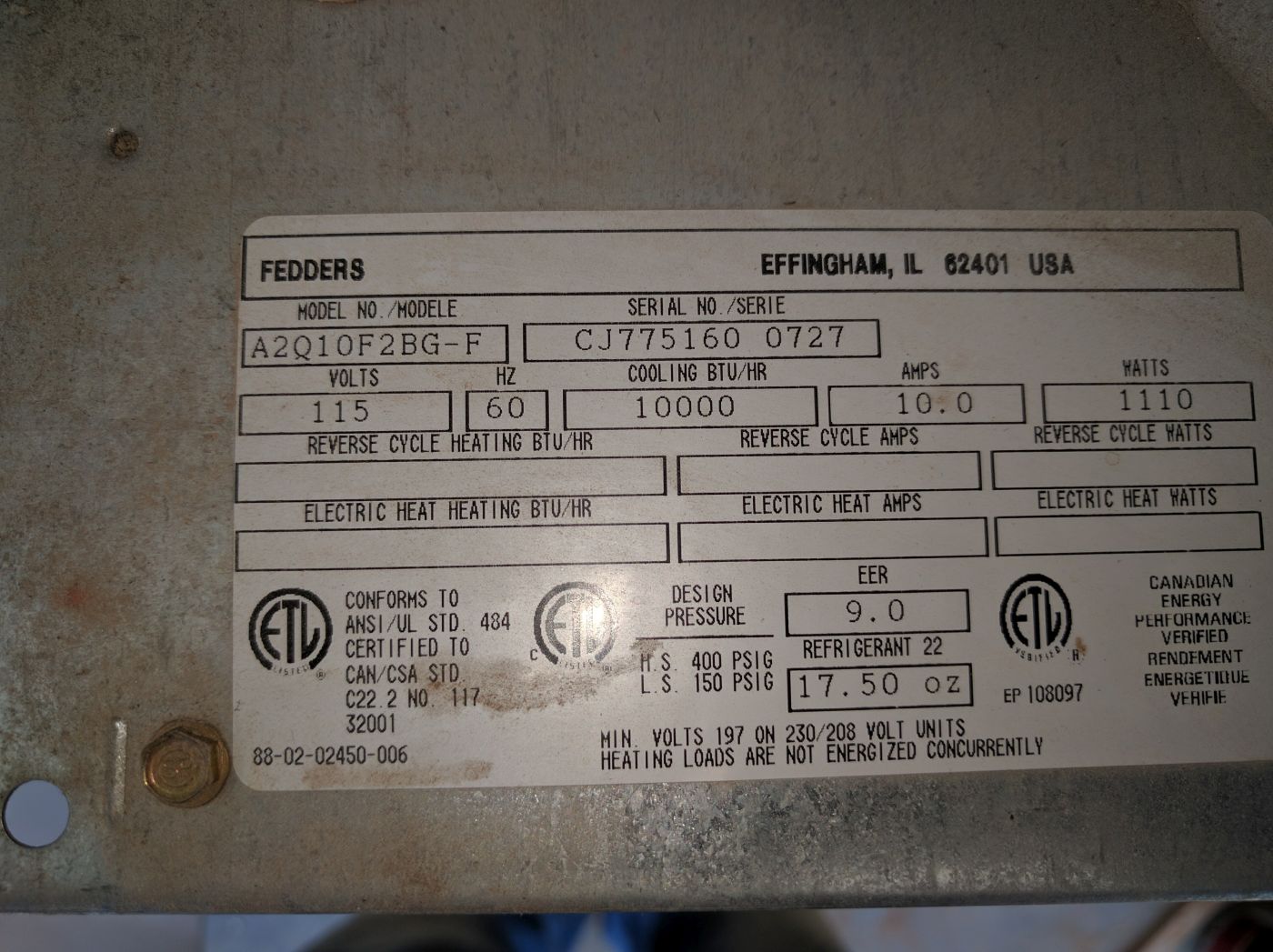
The test described below looks at how much these restrictions on the condenser cooling air flow effects performance. The tests are done on a window AC that I had had lying around. Its a 10,000 BTU/hr Fedders. At full cool, the nameplate says it draws 1100 watts. It has an EER of 9.0. So, its larger than ideal, but it should give an idea of what goes on. The AC is probably about 12 years old.
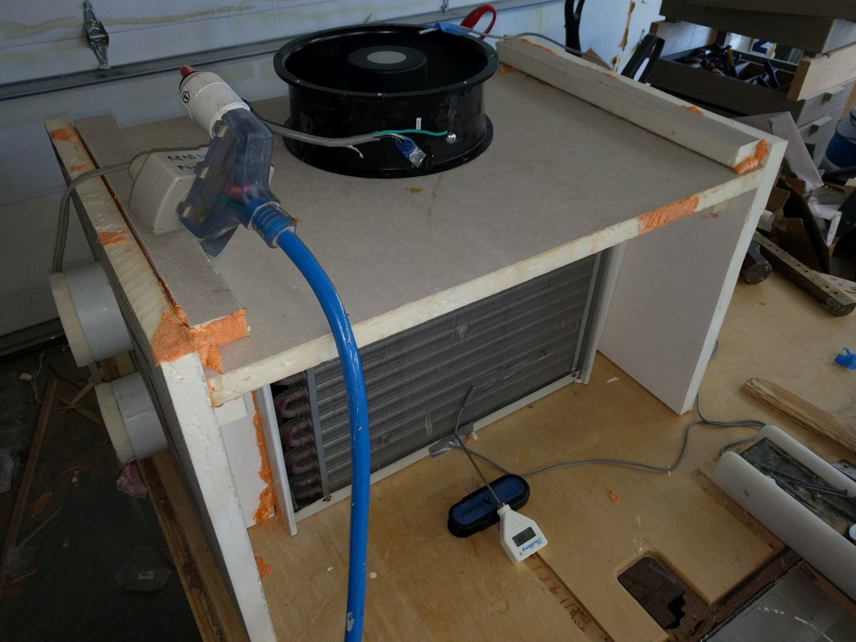
I built an outer housing for the AC unit that allows restricting the flow of cooling air to the condenser both on the intake and exhaust side. The amount of restriction can be adjusted by plugging some of the 4 inch pipe vents.
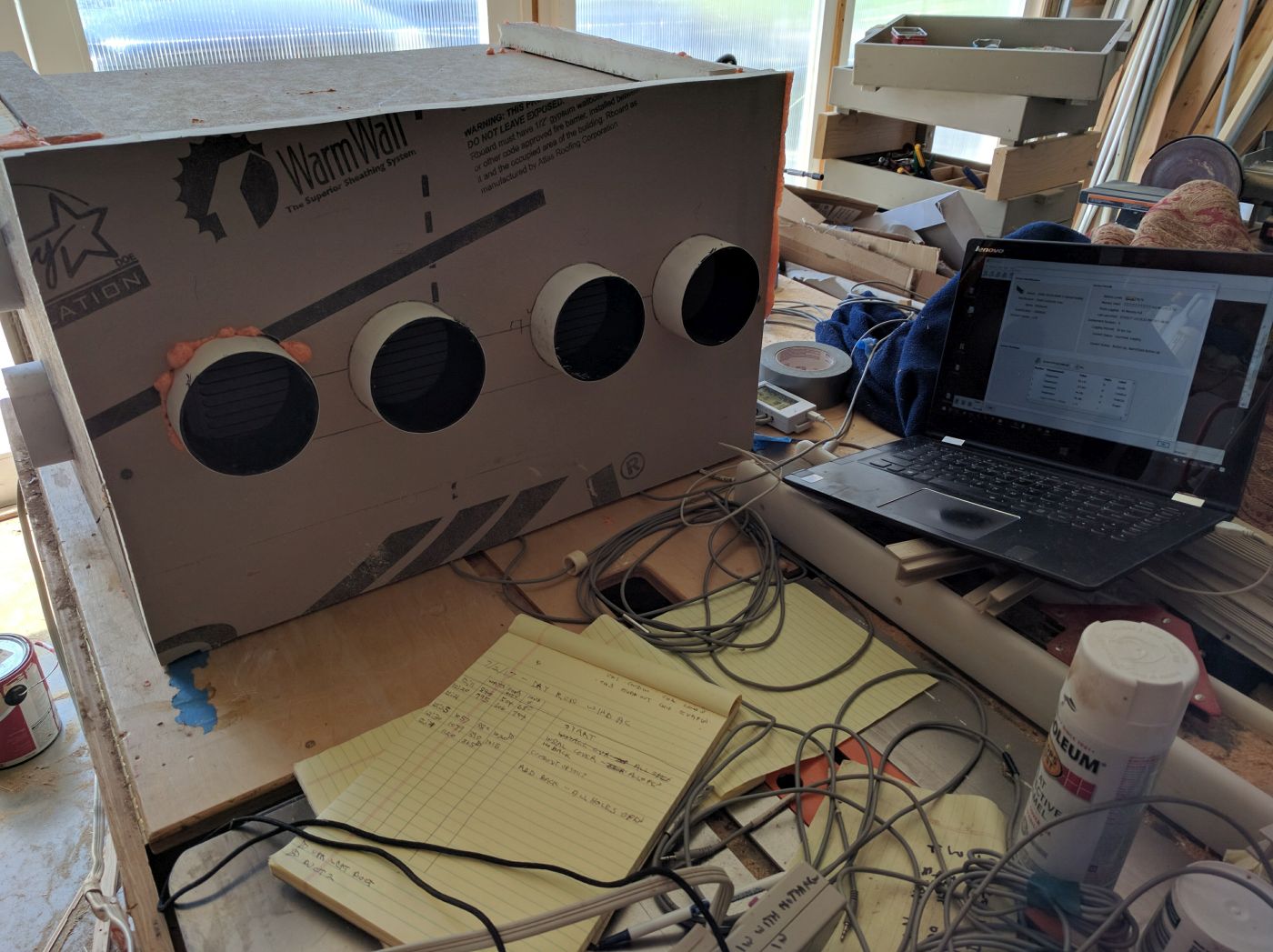
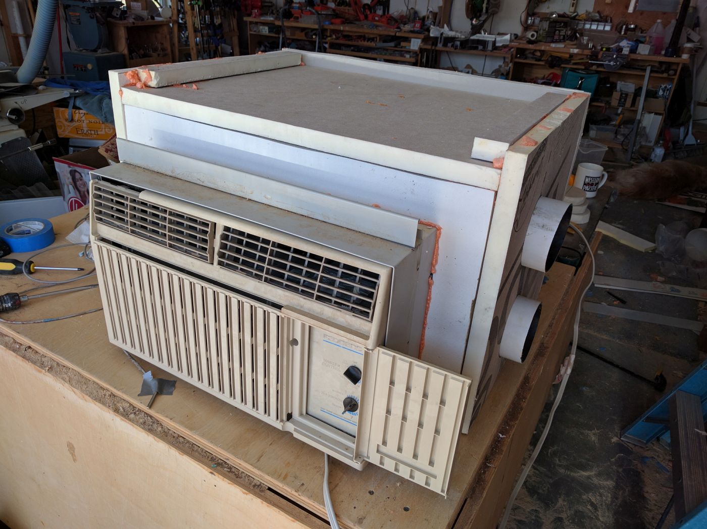
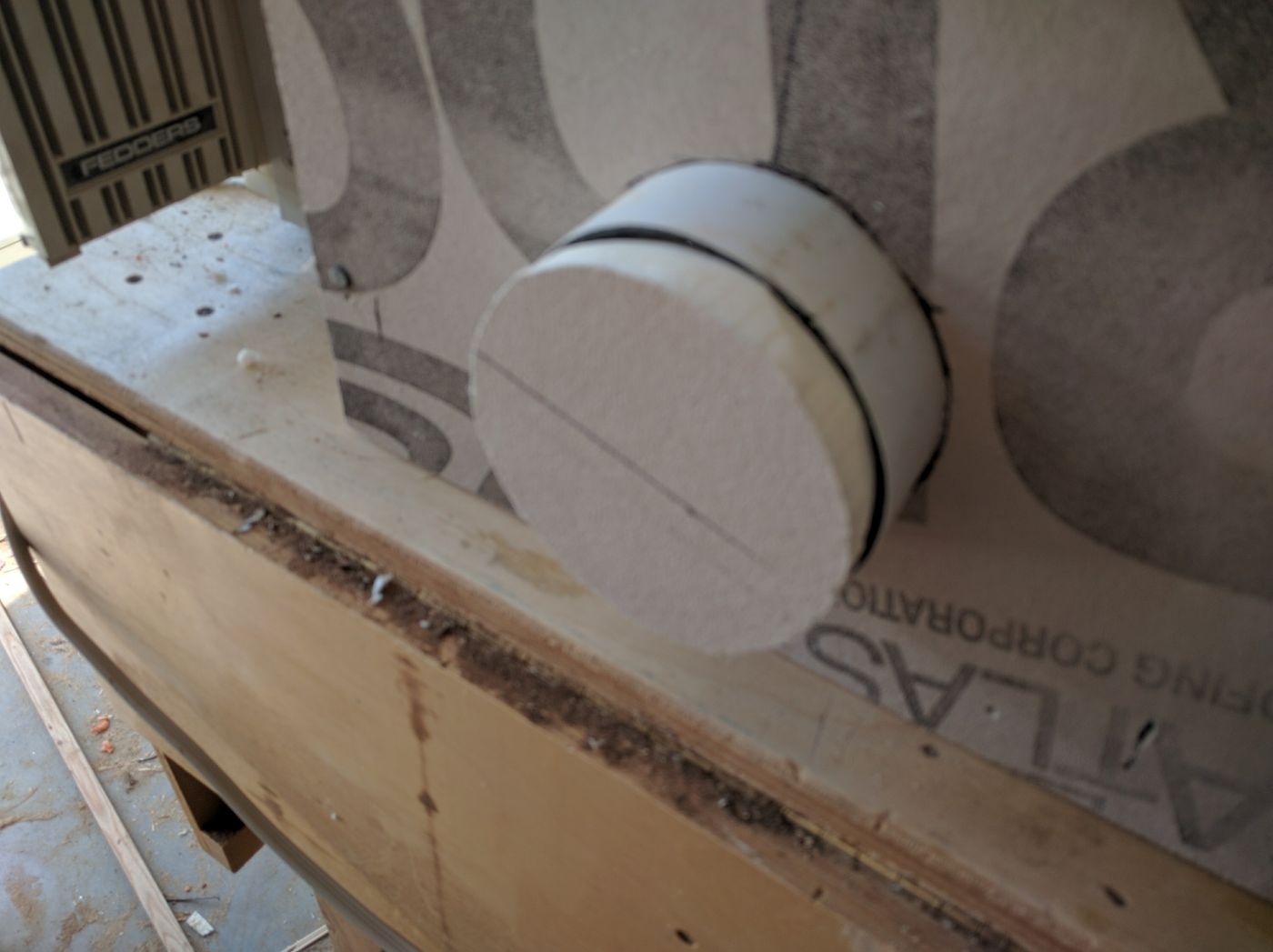
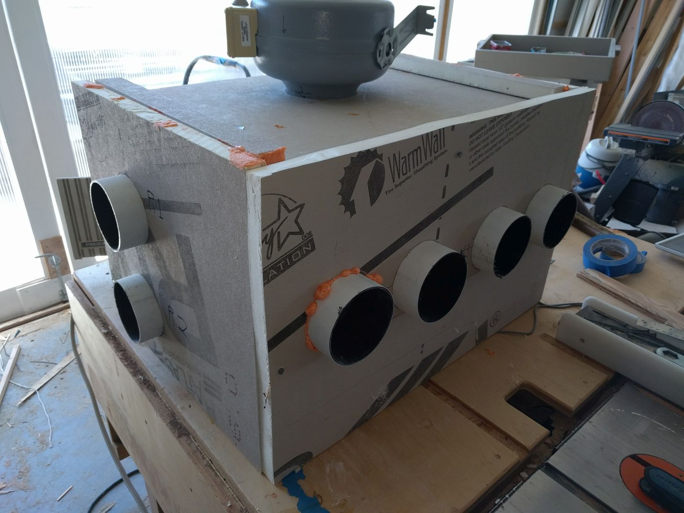
There are four 4 inch ducts on the sides that can be used to restrict the intake cooling air flowing into the condenser, and there are four 4 inch ducts on the back panel that can be used to restrict condenser cooling air exhaust flow. The back can be left off entirely to test for no exhaust flow restriction.
There is 2.5 inches of clearance between the added housing and the AC unit on the sides, and 4 inches on the top.
The pipes are nominal 4 inch (actual 3 7/8 inch ID).
There is also an added blower/fan on top of the housing that can be used to provide a forced flow of air into the condenser intake. To be tested later.
Results
The following five configurations with ever increasing vent area restrictions were tested:
- Basic AC unit with no restrictions (as a baseline)
- Condenser Intake: four 4 inch diameter ducts
Condenser Exhaust: no restriction at all — back not installed. - Condenser Intake: four 4 inch diameter ducts
Condenser Exhaust: four 4 inch diameter ducts - Condenser Intake: two 4 inch diameter ducts
Condenser Exhaust: four 4 inch diameter ducts - Condenser Intake: two 4 inch diameter ducts
Condenser Exhaust: two 4 inch diameter ducts - Condenser Intake: one 4 inch diameter duct
Condenser Exhaust: one 4 inch diameter duct
This last config made the AC go into some kind of protective mode and was aborted.
This table below summarizes the results — it shows how much the power consumption, condenser temperature go up and how much cooling capacity goes down for each increase in flow restriction.
Bear in mind that this is a 10K BTU/hr and most of the window ACs used in camper vans are 5K or 6K BTU/hr — so, somewhat less vent area may be needed for the same performance.
| Configuration number | 1 | 2 | 3 | 4 | 5 |
| Config: Cond Inlet | base AC | four 4″ ducts | four 4″ ducts | two 4″ ducts | two 4″ ducts |
| Config: Cond Outlet | base AC | full open – no back | four 4″ ducts | four 4″ ducts | two 4″ ducts |
| Condenser | |||||
| Inlet Area (sqft) | 1.125 | 0.33 | 0.33 | 0.16 | 0.16 |
| Inlet Area % reduction | 0 | 71% | 71% | 85% | 85% |
| Airflow (cfm)(1) | 871?(3) | 299 | 264 | 160 | 141 |
| Airflow % reduction | 0 | ? | |||
| Cond Temperture (F) | 112.1 | 122.8 | 135.8 | 147.4 | 160 |
| Cond Temperature % increase | 0 | 9.50% | 21.10% | 31.50% | 42.70% |
| Power | |||||
| Power (watts) | 1040 | 1130 | 1250 | 1390 | 1598 |
| Power increase % | 0 | 9% | 20% | 33.60% | 53.60% |
| Cooling | |||||
| Evaporator temp drop (F) | 36.8 | 36.1 | 34.3 | 31.9 | 31.2 |
| Cooling % reduction | 0 | 2% | 7% | 13.30% | 15.20% |
| Notes | |||||
| 1 – airflow velocity calcuated based on air velocity at the 4 inch inlet ducts. | |||||
| 2 – KillAWatt meter tripped and cut off power at this point. When AC was started without KillAWatt it went into a low cooling mode — overheat protection?s | |||||
| 3 – very approximate. Measured condenser outlet velocities at four points and averaged. | |||||
Parameters measured: power consumption, evaporator inlet and outlet temperatures, condenser inlet and outlet temperatures, airflow.
Airflow is estimated by measuring air velocities using a Kestrel Anemometer.
The area of the condenser heat exchanger is 1.26 sqft.
The area of the intake grills for the condenser cooling air is 1.125 sqft.
The exhaust grill on the AC is actually larger than the condenser coil so it does not restrict it at all.
Each 4 inch duct (actual ID 3.875 inches) provides 0.082 sqft of area, so 4 of them provide 0.33 sqft of area — an about 70% reduction in area compared to the intake grill on the actual AC.
The plot below is from the logger that was used to log the temperature sensors. The added numbers (1 throug 5) are for the various duct configurations (see above).
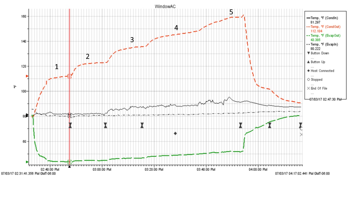
Red dash — Condenser exhaust air temperature (F)
Black solid — Condenser inlet temperature (F)
Black dash — Evaporator inlet temperature (F)
Green long dash — Evaporator outlet temperature (F)
Note:
I ran each configuration for 15 or 20 minutes to let the AC get to a stable condition, but you can see that the condenser temp is still going slowly up at the end of each test — so, the condenser temps shown in the table are not quite up to what they would be for a long run.
The plot shows the condenser inlet temperature rising toward the end, this was likely bad sensor placement, as the condenser air was just being drawn from the room (as was the evaporator intake air).
I tried to go down to only one 4 inch intake duct and one 4 inch exhaust duct. Very shortly after I did this, the Kilowatt went up over 1800 watts and started beeping (its only good to 1500 watts), and then tripped and shut off the power. I took the Kilowatt out and plugged the AC in again. In a short time it apparently tripped something in the AC — it continued to operate and produced some cool air, but condenser temperature and cooling output dropped. So, I guess the AC was saying enough is enough! I turned the AC off, let it cool off overnight, and it seems to be back to normal now.
Test With Inlet Fan on Window AC (much better)
This test looks at using a fan to force air into the condenser heat exchanger inlet. The idea being to try to achieve about the same airflow as the base AC operating free of any restriction.
Bottom line is that this worked well. It achieved essentially the same performance as the base AC with no restrictions on the condenser cooling air.
The fan is a Dayton 4WT44A from Grainger. It is rated 680 cfm delivering to free air . It appears to achieve about the same volume of cooling air through the condenser heat exchanger as the base AC operating with no restrictions does. The fan draws 25 watts, so only a small fraction of the 1000 watts the AC itself draws.
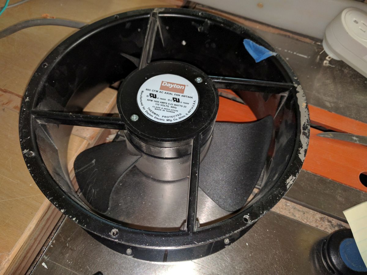
In the test setup, the fan blows air into the space between the cover over the AC and the AC to provide the condenser heat exhanger with cooling air. The performance of the AC with the cover and inlet fan is nearly the same as the bare AC, so this configuration works quite a bit better than the non-fan driven configurations of the first test (above).
One way to set this up in a van would be to have the fan fit tightly over an opening in the floor such that the fan blows air into the space between the AC unit and the cabinet/cover you have enclosed the AC unit in. The opening in the floor should be about the same size as the fan (so as not to restrict airflow), and the cabinet over the AC should provide enough space between AC and cabinet for good airflow. The cabinet needs to be sealed well enough to prevent air leakage into the van. The condenser exit must be vented out through the side of the van with a vent that is large enough not to restrict the flow — ideally about the same size at the AC condenser heat exhanger. The outlet vent could also be through the floor, but I think it would be hard to find enough area for a good vent.
Bear in mind that this AC is a 10,000 BTU per hour unit, so if you are using a 5000 BTU/hr unit, the fan and vent areas could be correspondingly smaller
- Basic AC unit with no restrictions (as a baseline)
- Condenser Intake: Fan pushes are through the condenser heat exchanger.
Condenser Exhaust: no restriction at all — back not installed. - Back to the Basic AC.

| Configuration number | 1 | 2 | 3 | |
| Config: Cond Inlet | base AC | 9″ inlet fan | baseAC | |
| Config: Cond Outlet | base AC | full open – no back | baseAC | |
| Condenser | ||||
| Outlet Area (sqft) | 1.26 | 1.26 | 1.26 | |
| Outlet Area % reduction | 0 | 0% | 0% | |
| Airflow (cfm)(1) | 811 | 814 | 888 | |
| Airflow % reduction | base | 0% | ||
| Cond Temperture (F) | 112.7 | 115.7 | 114.5 | |
| Cond Temperature % increase | 0 | 2.60% | -1.00% | |
| Power | ||||
| Power (watts) | 1040 | 1085 | 1065 | |
| Power increase % | 0 | 4% | -2% | |
| Cooling | ||||
| Evaporator temp drop (F) | 34.7 | 35.1 | 35.6 | |
| Cooling % reduction | 0 | -1% | -1% | |
| (1) airflow is from 4 velocity readings over condenser heat exchanger outlet — pretty approximate. | ||||
So, the fan forced cooling of the AC condenser heat exchanger provides the same cooling with no increase in power consumption (other than the fan) as the base AC.
Note that there is a discrepancy between the 680 cfm the fan is rated at and the 815 for so cfm in the table above — this is probably due mostly to the approximate way that I measure the condenser airflow — I just take 4 air velocity readings at the quarter points on the heat exchanger, then average them, and multiply by the heat exhanger area. So, not so accurate, but it does give a way to compare airflow between the base AC configuration and the fan forced air configuration. The result is that the airflow is very similar — which is good.
Fan: note that a lot of fans are rated on how much air they deliver when operating into free air (ie no resistance). This is not the case for this application — there will be some flow resistance and the fan has be able to produce good flow with this resistance. As a starting point, if using a 5000 BTU/hr Ac, I’d look for a fan that can deliver of the order of 400 cfm while working against a pressure drop of about 0.1 inches of water. This is just an educated guess, but maybe better than nothing. Good fan manufacturers provide a plot that shows airflow delivery vs pressure drop in inches of water.
Plot shows AC temperatures over the test.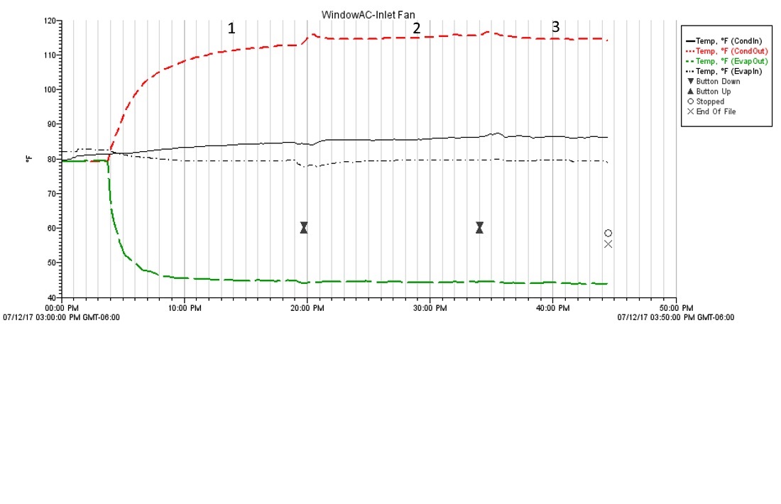
Red – condenser heat exchanger exit temperature (F)
Black solid — condenser heat exchanger inlet temperature (F)
Black dash — evaporator coil inlet temperature (F)
Green – evaporator coil outlet temperature (F)
Comments
Any comments, suggestions, ideas … are most welcome.
This is an older post but still good info for people like me wanting to do the same. I totally enclosed a 6000 BTU new unit in the back of my 5th wheel where the TV used to sit. I used four rectangular rain and bug-proof vents. These have large louvers turned down slightly.
For the condenser exhaust, two 10″x10″ opening vents. For the input air, one 10″x12″ and one 6″x14″. There is some restriction from the screens. I don’t know what the actual flow is. I did initially try just one 10″x10″ on the exhaust side. It got almost too hot to the touch and I wasn’t getting very good cooling on a 90+ degree day. Everything ran, just seemed to struggle. Added the second 10″x10″ to the exhaust side, and it is much better. I am satisfied for now. Each area is separated and well sealed.
A couple of exterior pictures – it is a clean enough look for me. The side picture shows the first evaporator input on the side, and the other evaporator input on top on the rear. The first exhaust out is below it – this seemed inadequate when running in 95 degree heat. The second picture shows the additional 10″x10″ condenser exhaust. The contour of the body forced the placement of those two somewhat apart. The exhaust grille is centered between them, and there is a 4″ opening gap the exhaust grille and the interior of the box. The exhaust air goes out both fairly evenly. After running for some time the air from each and the vent temps are close. https://photos.app.goo.gl/okoccNQqHEP6J6eq5
Oops, the second picture didn’t post: https://photos.app.goo.gl/goEFHDc29VNJhdDD9. I have a small generator that powers this unit and don’t plan on solar or battery/inverter use. Probably can’t run the a/c and the microwave at the same time on the 2K generator either! I will report after some actual use experience….
Hi Tom,
Good data – thanks.
Please let us know how it works out and if you make any more changes.
Gary
Hello again.
After searching to no avail, I decided to build the inverse of you: An entirely-outdoor, ducted AC unit. Surprisingly, this product does not exist. The closest thing I found to it was for dog-houses, but that product isn’t being sold any more.
Here is a pic of my hack: https://drive.google.com/file/d/1BBPjdl8LbNe6xZCkMCUm4HYGKiZ2ex3W/view?usp=sharing
It will live it’s life under my home, in an open-air crawl space. I will be controlling it with an Arduino.
The Arduino will act as a thermostat, and call for cooling by triggering a smart-plug. Upon power to the plug, the unit will cool the air in my home, without me hearing any compressor noise or worrying about any condensation leakage.
To ensure this would work, I needed to find a very “dumb” window unit, one that just has a couple switches and a dial for control. I peg the dial, and keep the switches in the ON position, then just control it by controlling the plug. I don’t use the thermostat on the unit itself (hence pegging the dial). Hope this helps someone.
Hi Josh,
Pretty slick.
Please let us know how it works out.
Gary
re: “An entirely-outdoor, ducted AC unit. Surprisingly, this product does not exist.”
Oh, those do exist, although normally they have much larger capacity than a window unit.
google: “What is an HVAC Packaged Unit?”
FYI: We’ve started using the Midea “U-series” (e.g.: MAW10V1QWT) on travel trailers, mounted just above the floor at the front. These have most of the advantages of a mini-split but installation is almost as easy as a normal window A-C. The condenser section extends out about 11 inches, and it does need external support (a basic bracket is included with the unit).
It might be possible to mount one of these in a cargo van rear door if the hinge & internal support structure is beefed up enough to handle the weight (~55 lbs).
Hi Elvis,
Looks like a nice unit – especially with the CEER of 15.
I have a 2nd spare tire mounted to the back door on my van that weights about the same as an AC. The door skin is reinforced, but not the hinges or latches.
So, might be able to mount the Midea on the back door without a whole lot of enforcement.
One thing that bothers me a bit about the 120VAC units in a camper van is that the heat generated by the inefficiency of van inverter goes into the van as heat and just requires more output from the AC. I wonder if it would be worthwhile to cool the inverter with out side air?
Gary
It sure would be nice if there were more direct current air conditioner options. There are the very small (2k-3k BTU/Hr) cabin cooler units that use Secop (formerly Danfoss) compressors more commonly found in refrigerators, a few rooftop mount units to help big trucks meet “no-idle” regs. (e.g.: Kingtec), or a few mini-splits (Hotspot Energy). Other than that, gotta use an inverter.
Even some major air conditioner manufacturers (e.g.: Lennox) are (or were recently) marketing “hybrid” condenser units that are actually regular 240vAC units with an add-on integrated inverter. so it’s possible to do that in this camper-van A-C application too, as long as the inverter manages to handle the start-up load. The inverter heat should be pretty minimal, but if it’s dedicated to the A-C it could be mounted so that waste heat is vented to the outside air.
IMO, the ideal Air Conditioner in a van (at least in terms of space efficiency, if not thermal efficiency) is the OEM A-C that’s under the hood… but unfortunately the only ones that run off of batteries are on hybrid vehicles… and none of the US-market vans suitable for conversion are available in a hybrid. Maybe Ford will eventually offer a hybrid Transit? Or maybe an electric compressor from another Ford model could be retrofitted (but in this day of computer-module controlled everything, that’s unlikely).
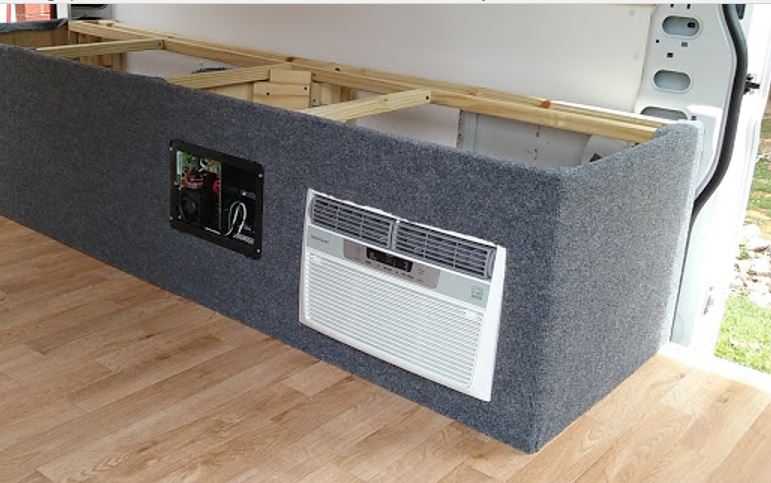
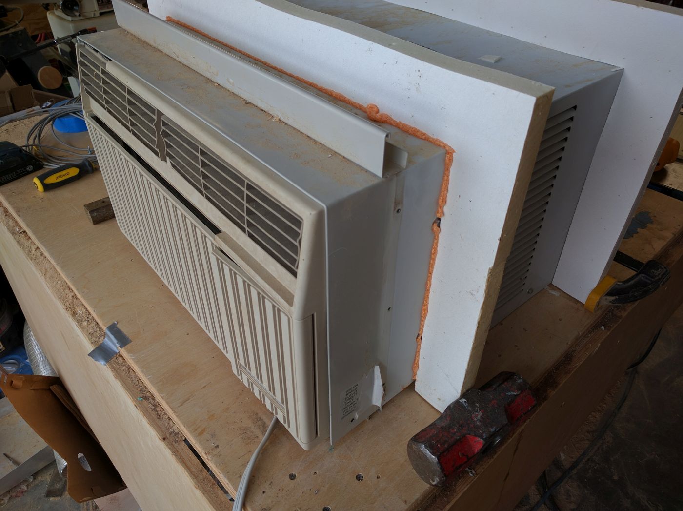
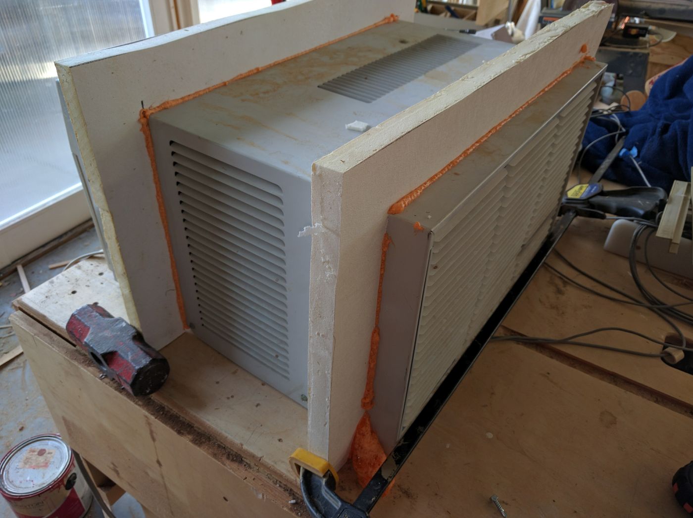
FYI: The photos at the top show a window air conditioner sitting on a wood floor inside a plywood box. The inside bottom of this enclosure is not shown.
But if intending to operate the air conditioner when the vehicle is parked on a slope, a provision must be made to allow condensate drainage. The OEM drainage path works only if the unit is relatively level (outside end slightly lower). If the vehicle is parked on even a slope that causes the front of the A-C to be lower than the back, the condensate will overflow the relatively shallow OEM internal drainage pan, and possibly leak into the vehicle.
For what it’s worth, I’m cooling 700 square feet of a house with a little 5000 btu window AC.
I mounted it in the 26″ wall sleeve of the former mini PTAC that was there but had failed. Since the replacement PTAC was $700 and the used window unit was only $50 it was worth a try.
Here’s the wall sleeve: https://www.acwholesalers.com/Amana-PBWS01A/p100211.html
HOWEVER It didn’t cool effectively until I performed the hack shown in this picture: https://photos.google.com/photo/AF1QipNnsCUTDhH2OOkUGbwUhxnySh-hGnRb0v8luULF
It was a matter of separating incoming and outgoing condenser airflows.
My point is that an oversize box next to the wall of your van is the cheapest and easiest way to accomplish the project.
In this case the project is to use a window unit without having it protrude from the wall of the van.
One just needs to find or make a good looking louver. The one that comes with the wall sleeve doesn’t cut it: https://photos.google.com/photo/AF1QipNGm9NXZuYp38tKz3xVP1kO9ORc2eAfJbATeNe2
Hi Kevin,
Thanks!
The 2nd link to the picture does not seem to work – any chance you could fix it?
Gary
Here’s a nicer LG grille:
https://pisces.bbystatic.com/image2/BestBuy_US/images/products/4861/4861737_sa.jpg;maxHeight=640;maxWidth=550
Mine is Amana and it just looks cheap and too easily damaged for an RV:
https://lh3.googleusercontent.com/jcaugdcH8c_SFoOzxJhqKTOuGnprdlQOze7ZmLak2pRe5xB9nFyuAuMeTgaWe4S2kAvkSUBTdV_XSxx8RdRuYEuxeWs_B6RH0CPJ5l41e_pYL-WjW96vXSVmxsWsDtj6DS0uQNRJLtJadgPR6SG6lq26vVmG1tzjeLPak36WhwwT5kRfunRL7Ot_0zW_ggH4Hdo7VFRRtPWUHdAev6ZzJA9csv9u0ZO7AtDYEHubnDdcgzV_CQxezI-LgQLZjMV6CIDeoP2vHKnLyWBlcqgicAH9X8n777bAEdiJU4WmldQnltM9QywEebHvnCdbHAYC6-KdEt74Yo98HB1EgbK45FQWBIHMN8gyooH6Z18KDgul9GJvvConvk_yKbIQ9quofZO6HgdLIBDO7POCY4XQqrxZnfuMjp_0IQlamJxNegHbns8uXDW0tPH_qzB5oPdbN8IaF8pwbOPBqv87uR9AnA9MogVBlLt2zEOs6YmhIx41F3pYem1qAdSGr9o3d937szLc1ZZwZKJotZXb_NNpA5BrG2qpS15p5dSuBBFc-sOuz-HIdRwgloC-kXvOdQJhUX95xRPI9RDHIeeUeJC73hPy0kINt1_rWhJ408tyDzapgBSKJnQp7z98LZYIFB2aoX-SHBYWbIke2JMAn4nbcyCbsu7ib5KVXtIrtk5me7j2BnIu7hFiL7LSkraL6_Pu_EFgc6tCpnx9gWXyZJgM3PTiGQ=w758-h568-no?authuser=0
Amazingly explained! I am getting curious about the way you are using a window air conditioning unit to cool camper van conversions. I have seen a lot of blogs & videos it but this one is simply awesome. I will definitely give it a try.
Hey Gary.
Thanks for the write-up and testing.
I was wondering about an inverse setup: Have the entire AC unit outside, and only duct the evap-coil (front) of the unit, leaving the condenser-coil (back) of the unit unmodified.
Do you think this would be a more machine-friendly solution?
I know these units are sharing a blower for both the evap and condenser side, so restricting one side is likely putting a stress on the other. However: Openings for the evaporator-side of these units are already restricted by design (compared to the condenser side).
Essentially I want to turn a window ac unit into one of the (now discontinued, and apparently faulty) ClimateRight units seen here: https://climateright.com/products/cr2500ach?variant=34672044671128
Thoughts?
Hi Josh,
I’m not sure — I think you would have to give it a try with the actual duct size you would connect the evaporator to to van with. It does seem like the evaporator side flow is less than the condenser side flow, so it might be easier to get good efficiency with the hookup you describe.
You could do some testing with various duct sizes and see how it works. A KiloWatt meter would give you some idea when you are restricting the flow too much.
Not that it matters for what you plan to do, but those ClimateRight units appear to have pretty low efficiency (low EER) – so, a good, high EER window unit is probably a better bet for efficiency.
Would like to hear how it works out if you give it a try.
Gary
Window AC unit choices are bumming me out.
There are very few all-in-one HVAC *Window* solutions, which is strange to me because pretty much every mini-split is an all-in-one HVAC solution and they share the nearly identical mechanical parts to window units.
The search for the following is proving futile:
– Low BTU (aka: small size, and no clam hands)
– Heat Pump (aka: reverse cycling and not just resistive heat)
– Defrost Feature (aka: ability to operate heat-pump below 40F)
– Fan on Demand (aka: ability to leave the unit ON without the fan always running)
– Inverter Compressor (aka: quiet / most efficient tech)
The only unit I found that comes close ( Amana AH093G35AX ) lacks the inverter tech (so it’s only 9.9 EER, and perhaps noisy). It also lacks the defrost ability, but makes up for it with an additional resistive heating function for below 40F (at the expense of power-use since it only comes as a 240V unit).
It’s frustrating that no one seems to take true advantage of the relatively simple reverse-cycling of an AC window unit to get HEAT. So many of the newest and most efficient window units seem to completely abandon heat, or have it as a lame after-thought.
If you know of a good all-in-one window HVAC solution, I’m all ears. But for now I see two options:
Option #1: Buy the Amana AH093G35AX.
Option #2: Buy a conventional AC only unit, and also buy a common (resistive) area heater.
Hi Josh,
Yes, that does seem strange that the combo heatpump/AC units are not common.
There are some small mini-splits that people have used in RVs, tut not sure they would fit your needs or be small enough in BTU/hr to work for you.
I’ve put together some ideas on various cooling schemes on this page — might be worth a look:
https://www.buildagreenrv.com/design-and-build-information-for-camper-vans/cooling-and-air-conditioning-for-a-camper-van/
I would be careful on going too low on the cooling capacity. There have been people who have successfully used 5K BTU/hr units on well insulated vans, but I don’t think you will be happy with anything less for hot/humid conditions. If you search the ProMaster forum for posts by Jracca, he has a detailed description of how his 5K unit has worked out.
You might also try posting your question on the ProMaster, Transit and Sprinter forums — there might be some ideas there.
Gary
“It’s frustrating that no one seems to take true advantage of the relatively simple reverse-cycling of an AC window unit to get HEAT.”
Agreed. The evaporator fin spacing of a typical window unit is too tight, so it’s a major redesign.
Hi,
Please let us know how it works out.
Gary
I purchased an old pop up camper with ac on the top. I removed it due to leaks. I have instilled a window unit where the hot water unit was originally. It fit perfectly and the exterior door is vented. As I read your article, I get lost with all the details. (I’m not a havoc person.) My question is how did you deal with the water draining from the window unit?
Hi,
You might find the answer on this page:
https://www.buildagreenrv.com/design-and-build-information-for-camper-vans/cooling-and-air-conditioning-for-a-camper-van/
As far as I can recall, the window ACs have a slight slope toward the outside so that the water coming off the cooling coil runs outside if it does not first evaporate?
Gary
An HVAC tech might approach this problem by moving the condenser section into a separate section from the evaporator section (which would require cutting the lines, brazing, evacuating & recharging). That would basically turn a window A-C into a mini-split unit.
So, instead of trying to shoe-horn a window A-C into the interior of a van, why not use a small (9,000 BTU/Hr) mini-split unit?
A small mini-split would be a *LOT* more efficient than any window air conditioner, and heat pump versions are readily available.
The other option is to use a dual hose portable A-C. Not as efficient as a mini-split, but better than a window A-C with the added fans required to make it work in a van.
Hi Elvis,
I guess its all a bunch of tradeoffs…
The window AC offers an efficient (EER 12 for the best of them) in a very compact package for very little money.
I did recently see an installation down low on the back door of a ProMaster that looked pretty good and looked pretty straight forward to do and that should give full window AC performance since there is no need to redirect any of the flows.
I did see one very detailed description of an installation of a window AC where they did separate the condenser and installed it below the floor. It was very complicated and time consuming — just can’t see many going that way.
The mini-split are promising and I mention them on the AC page, but not all that easy to fit one in, and not much choice yet in the size needed.
The numbers I’ve seen on the two hose portable ACs show about the same EER as the window ACs. People do use them – on the down side, thet take up a fair bit of floor space in a small van, but on the plus side you can just take them out on trips where no AC would be needed.
Lots of choices.
Gary
Aside from cost, the biggest advantage of a 5000BT window AC is weight. Try finding a portable A-C that weighs only 40-lbs. There aren’t any under about 60 lbs.
Same problem for mini-splits, but the smallest ones are 9,000 BTU/Hr. However they are a lot more efficient: up to 15 EER & 25 SEER, along with which comes an invertor-driven variable speed compressor, so there’s fewer problems with startup surges compared to the on-or-off cycling of a cheap window A-C.
I am in an RV and the bedroom window is an inch too small vertically to fit the smallest window AC. :/
So, I was thinking about doing a build like the one shown near the top of the article, in the cabinet, but I can’t find any more info on that.
In my case the side intakes would be free and clear, taking in the air in the RV (sitting on a built in dresser) and I would encase the heated output off the back and direct it out the window. It is a near match so the back would not be blocked.
Would that work? Am I missing anything?
Hi Mandi,
There is a bit more detail on the window AC install in an RV on these pages:
https://www.promasterforum.com/forum/showthread.php?t=65489
and
https://www.buildagreenrv.com/design-and-build-information-for-camper-vans/cooling-and-air-conditioning-for-a-camper-van/
I’ve also saw one in which the window AC unit was placed low in one of the rear doors of a ProMaster van. It looked pretty good, and since none of the flows had to be redirected, it should perform quite well. Just another option.
If by side vents, you mean the louvered openings on the side of the AC unit, then you don’t want those openings to vent inside the van. These openings are inlet air to cool the hot condenser coil, so the flow is into the side louvers, through the condenser coil and then out the back of the AC. If you use air inside the RV to feed these, then that air will have to be pulled into openings elsewhere in the RV, and it will be hot outside air. You need to connect those side vents to outside air.
Gary
I had the same problem… Did you check the LG LW5016 & LW6017R (sold at Home Depot). These have the lowest height required – slightly over 11 inches (less than the stated height of 11.13) – of any window air conditioner. They also have very low power consumption (440w & 520w), and slightly better humidity removal than most other 5,000/6,000 BTU A-Cs
Gary,
Great website, love all the detailed information.
I have a small travel trailer (16ft) with a very noisy roof AC (and no roof vent) that rarely gets used, but when it is needed it is a necessity. I have been thinking about improving the situation for a while now and your discussion is very interesting.
Here is what I hope to accomplish: replace ac with a small 5K BTU, quiet, less expensive, lighter, window AC. Move the weight off the roof. Use the roof opening to install a fancy vent/fan. The plan is to add a nicely sealed door and a heavy duty slide out drawer to the side of the trailer. To use the AC: the door would flip open, AC slide out and seal around door opening. This would allow for the ac to operate as intended, keeping the hot stuff and noise outside. It would be made to be “universal” to facilitate easy replacement of AC unit.
It’s a big project but doable. I will send an update when completed.
Regards,
Craig
Hello,
Interesting read, In my case, I have a small Scamp trailer and mounted a 5k btu GE Window unit in a very small space that was about 13” high 18” wide and 21” deep with portioned fresh outside air and used 2 50cfm bath fans mounted on the side (directly behind the condenser) with each fan venting thru the floor with a 3” hole. The fans turn on with the ac and works great. The bench/Bed above the ac just barely gets warm when running at the coolest setting all day. Using the side by side fans to exhaust condenser heat as opposed to pushing in fresh air for me seemed to work best in my application.
Thanks Frank,
Sounds good.
Any chance of getting some pictures?
You can email the pictures to me, or attach them to a reply.
email here: https://www.buildagreenrv.com/contact-gary/
Gary
Gary
I just found this website and this thread – came here for installing windows in a sprinter. I have a 2006 Dodge/Mercedes sprinter that has only windows in back doors and up front (windshield and doors). But I then saw this discussion on air conditioners. Even though I didn’t read every word you guys have written about the topic, here is what I did. I bought a $250 portable 8000 btu air conditioner that sits behind the driver’s seat and the exhaust hose is attached to a custom made 1/4″ plywood piece that fits inside the driver’s window taking up about half of the window (from top to bottom) so I close the window to hold it in place. When connected to shore power I plug it in with its own extension cord (using a splitter) and it works like a charm. I can leave it in place or pull it out a bit and direct the air toward the back and get a great air flow and cool down. If the van has gotten super hot and the outside temp is in the 90s then it has to work pretty hard but it can do it. Just thought I’d throw in my 2 cents.
Thanks Andrea,
What brand of portable AC are you using?
Gary
Hi Gary, Its an LG that I bought from Lowes 2 years ago when I first got this van. It does take up some valuable real estate but has been worth it. I have been on this trip 9 weeks now (California.Oregon.Washington.Alberta.Montana.Utah).
Very happy to find your site, very good! Thanks.
Hi Gary,
I summarized my window AC testing few days ago and created a PDF encompassing the write up, data and photos of test set up equipment and sketch of proposed plenum build.
The PDF was updated to version 2 yesterday.
I will be going on vacation next Wednesday. Is there anything else you need?
Santiago
Hi Santiago,
We are up in Yukon/Alaska with VERY limited internet – none at all most day.
Thanks very much for putting the pdf together and will have a look once we get to good internet.
Thanks,
Gary
This is how you would mount a cheap window AC to function as a heat pump for heating the RV in winter.
The COP will be 3+.
In this case, however, you need to exhaust the cold air, and deliver the warm air to the space.
Also you have to defeat the thermostat, but this is done by jumpering around it. This is easily done with the dial thermostats, not so much with a digital model with remote.
A 5000 btu unit would provide plenty of heat for an insulated van, so this could be a good choice for those of us trying to go 100% electric in colder climates.
I haven’t found anyone actually trying it yet, one unknown is the how cold can it be outside and still have it provide heat. A plug in style 120V thermostat could provide automatic operation.
Hi Kevin,
Was there supposed to be a link there showing the proposed AC mounting?
Gary
Hi Gary,
Here’s a quick sketch.
You’ve made a box to blow ambient air into the cavity that encloses the condenser and condenser fan.
In order to use it as a heat pump, we just reverse the box.
I’m proposing that the box should enclose the “user side” of the unit. Now the window AC provides heat to the camper from the condenser side, and the cold air from the evaporator is removed from the space.
I also don’t want to hijack the thread because it’s about cooling the van. I’m interested in heating the van with a $120 “heat pump” hack.
Nice — quite a “cool” idea.
Maybe efficient enough to make electrical heat practical.
Please let us know if you try it.
Gary
Hi Gary,
I did try it and it iced up quickly at 45F outdoor temp in relatively dry Denver.
So basically a failure.
Thanks Kevin.
Gary
Hi Gary,
You are right, I am guessing what the pressure drop will be through the AC and as it loops through that and back down to the floor. Think enclosure, ducts, condenser coil and getting around the condenser propeller fan.
What I need to do is to measure the new AC sitting on a bench with no restrictions and am crossing fingers that its’ design condenser cooling flow will be a lot less. If so then I can drop down to the EBM-PAPST 143 series that is smaller quieter and consumes 29 watts.
Granted the EBM-PAPST 200 series (61dbA) is not great noise wise. The next smaller model the 143 series (58dbA) is better but still 1 dbA higher than the Dayton 10″. High fan RPM is not our friend.
Looking at http://www.fsec.ucf.edu/en/publications/pdf/FSEC-CR-1674-05.pdf
PDF page 5 under heading “Impact of Air Flow on Outdoor Unit Condenser”
“The total external static pressure of the original fan producing approximately 2,200 cfm was about 0.12 iwc.”
This is my pressure drop starting point. Then there ducting losses. I have no idea what it would be on a small window unit operating with 30,000 fewer BTUs. No doubt condenser tube/fin design as well as air velocity determines pressure drop so it might be a realistic number from large to small units?
Once I have a real unit to play with and get baseline flow data I should be in a better position to decide on fan. The Dayton 10″ I believe I can purchase on eBay for a lot less than Grainger. I should be able to squeeze it in. Its’ fan curve makes me nervous due to potential pressure drop from floor inlet to floor outlet. I realize the AC has a propeller fan pushing through the coils. Would the propeller fan assist or hinder the Dayton 10″ ? I am not smart enough to predict that. All I can do is try the 10″ Dayton, cross fingers that it can get the AC units’ design cfms end to end. Am partial to low noise and power consumption.
Appreciate your fan offer but I think I will look at eBay again. Should the Dayton not work out I have another project I can use it on and it’s perfect for it. Plan B would be a fan with fan curve that pushes the cfms through.
Gary as always, thank you for your input and different points of views. I like learning and this is the site to do so.
Santiago
Hi,
I’m not sure exactly what they mean by total external static pressure of the fan in the pdf, but I’d guess it includes the pressure drop through the condenser itself. On the window AC, the built in fan in the AC will handle all the pressure drop through the condenser and the internal air path — your external fan only has to handle the pressure drop you add due to your added ducting outside the AC.
It is hard to estimate your added ducting pressure drop, but you might find the calculators listed on this page: https://www.builditsolar.com/References/references.htm for “sizing pipe, ducts …” But, its probably going to come down to just trying a fan and seeing how it does on maintaining airflow that is about equivalent to the base unit.
One item you might consider for both testing and the final setup is a motor speed controller — depending on the kind of motor the fan uses, the motor speed controller might let you adjust air velocity and fan noise to to the lowest value that still gives good performance.
https://www.amazon.com/Casolly-Variable-Controller-Exhaust-Inline/dp/B07BMR4THQ/ref=sr_1_3?ie=UTF8&qid=1532619980&sr=8-3&keywords=fan+motor+speed+control&dpID=51yXEx7TDnL&preST=_SY300_QL70_&dpSrc=srch
I’ve used these on several blowers to good effect, but have not tried it on the Dayton fan.
Gary
Hello Gary,
Unfortunately, the AC will arrive 8/01, the Kestrel 1000 is on its way. No fan order until I get basic numbers. Meantime if heat wave subsides a bit will start shopping locally for square tubular steel as it’s backbone of all cabinets, covered with good looking surfaces wife picked out that hides the steel frame.
You make a convincing argument that the ACs’ condenser propeller fan will hold its’ own. With that I think the Dayton 10″ is the one. I prefer the smaller EBM-PAPST models but to get that performance they generate more noise. Not good.
Initially, I thought of DC fans. In this flow range it was 24vdc and higher. Also not as quiet but I wanted to adjust speed for varying operating environments. I know I can step 12v to 24/48vdc but it was the noise level.
Then EC fans, promising speed control but again not as quiet in the flow range I think I need. The Dayton 10″ you use is not rated to be controlled per Dayton, it uses a PSC motor and I can see why Dayton adds those warnings. So it will likely be the mild manner relatively quiet Dayton 10″ unless next week’s flow data states otherwise.
On the Florida Solar research pdf, if you read the paragraph where I hand copied the line I wrote it explains that yes they were after the pressure drop through the test condenser. I could be wrong but that’s what I got from that.
Thanks for reminding me to calculate whatever traditional ducting I plan on using for pressure drops. It will be minimal as the biggest “ducting” I see is the enclosure itself as it guides the air stream exiting the fan into the mid section of the AC unit feeding the propeller. After passing through condenser coils heads down towards the van floor exit opening then once outside turns 90 degs and is whisked away.
I think I will remove the ACs’ metal housing or at least open it up big time as there is an insulated and sealed wall between the cold side (evaporator) and hot side (condenser). Why restrict cooling air with weather protection vents you don’t need? Will not permit flow to short circuiting condenser.
Welcome more ideas, comments or suggestions. Meantime will wait till I get flow data next week. Thanks for all you do.
Santiago
Hi Santiago,
I will be following your progress with interest. I am contemplating a similar plan for my Promaster conversion. I picked up a 6000 BTU A/C when I was at Costco the other day, but it is currently sitting at the bottom of a stack of other project equipment.
Like you, I had originally thought about both the intake and exhaust going through the floor. I am now leaning toward a floor intake, with the exhaust going out the lower rear quarter panel. This area currently has the existing one-way vent for door closing. It is also hidden behind the plastic trim on the outside. The thought is that the vent can be exposed when using the A/C, but it could be covered by the plastic trim the rest of the time. If you come up with a workable plan for both intake and exhaust, I might try to copy, although my layout leaves the center aisle open as a walkway, so my “garage” floor is more limited.
As I’ve read some of your posts, I’ve started to wonder if replacing the existing condenser fan with one that maintains the same flow at a higher pressure drop might be an alternative to adding the Dayton fan. I guess I need to pop the case open sometime and get the nameplate info off the existing fan/motor to see if that might be a possibility.
Thanks to both you and Gary for the good ideas and for taking the time to post them.
Andy
Hi Andy,
Glad I am not alone doing this.
You bring up two interesting points.
The rear quarter hot vent, what do you mean by “the vent can be exposed when using the A/C, but it could be covered by the plastic trim the rest of the time”?
I am totally in favor of opening the condenser exhaust vent to the outdoors when using the AC then closing afterwards since it will only be used while parked. I know the vans’ bottom wall area is double hulled and covered with black plastic pop out covers. Have you found that to be the case way in the back where the vans’ air vent is ? Honestly, I haven’t looked there and you might be on to something! To be clear, you mean exhaust through the existing air vent, onto an existing van cavity that obviously vents to atmosphere … right ? Will take a closer look tonight.
If that does not pan out and it sounds like your AC grill will face the center hallway, look to see if there is room underneath for the exhaust vent. Mine has the AC grill around 6 inches forward of the wheel well and more or less centered. Am fortunate that the intake/exhaust will land right about a large free floor area.
As to replacing the ACs’ propeller fan with a more powerful AC fan, hard to predict the outcome. That would require testing after the AC is installed and plumbed in as you need to consider the install as a new “system” from end to end.
Will comment on the test results I see next week and hope that offers some direction. I plan on constructing a temporary enclosure that matches the one designed. After all baseline data is recorded, add the fan and exhaust the same way I am planning so to simulate the actual van install on the bench. One concern I have is the throw beyond the condenser. If back wall is too close will that affect performance? I’ll find out. Obviously I also need to preserve my garage space.
Thanks for your ideas Andy.
Santiago
Hi Santiago,
I’m not sure if there is a way to paste photos here in the comments, so I will attempt to describe my plan a little better. It is still just a plan and I may find that some of my assumptions are incorrect.
My idea would be to remove the existing air vent “fixture” in the rear quarter panel since it is a little small (5″x5″?) and likely has too much restriction (I assume that the doors will still close OK with only the vent on the passenger side, but will need to test by taping one side off). I would then cut a larger hole in the rear quarter sheet metal (8″ diameter or maybe 8″x8″ looks like about the max possible) and then put some sort of grill or screen over this hole in the sheet metal. This would be hidden behind the plastic trim (the door “vent” simply vents out between the gap between the plastic trim and the sheet metal, but this has a relatively small area). I would then make a cutout in the plastic trim that is the same size as the cutout/grill in the sheet metal. The cutout piece could just be removed when the AC is running, or maybe hinged and flipped up to expose the exhaust vent grill. When the A/C is not running, the cutout in the plastic trim would be covered with the piece of plastic that had been cut out. You would still be able to see the outline of the cutout, but hopefully it wouldn’t be too noticeable. If I ever decide to eliminate the A/C completely, a sheet metal patch could be installed with the original door vent and then it would be covered by a replacement plastic trim without the cutout. The modification to the sheet metal wouldn’t be visible from the outside.
Anyway, that is my current thought. Like I said, I originally planned to have the vent in the floor, but was a little concerned that my intake and exhaust would have to be right next to each other, and didn’t know if I could direct them well enough to keep the exhaust from recirculating to the inlet.
If we can’t find a way to share photos via Gary’s site, you can contact me directly at friedl.andy@gmail.com.
Hi Andy, Santtiago,
Added a plugin to allow pictures to be attached — look for the picture on this page for instructions.
Once you guys get further along, we can added a dedicated page for your projects with detailed description and pictures.
Thanks!!
Gary
Hi Andy,
No photo needed just yet, your explanation is clear.
If your floorplan has the AC on one side or the other with AC cold discharge facing center of van, I can see why you want to vent through the van wall. I lucked out as my AC will be almost centered and discharging cold air towards front of van. Cold discharge will be about 3 feet off the floor.
The black plastic trim “hidden vent door” could be very difficult to pull off. Issues that while not impossible would be hard for me to deal with are careful cutting and matching of trim with no more trim material for a redo, hinging and water sealing. Maybe you are a very good craftsman but that would make me very nervous. I always mess something and need replacement material. As plan B, my plan C, you might want to consider a similar vent scheme a little higher over the trim and through the sheet metal wall.
Ok, if you are over the smelling salts and back on your feet, think of metal cover with seal all around and securely attached. It would be painted same as van. Just put plate back when done using the AC. You would still have sealing issues but …. it’s plan B. If I ever implement this scheme I will use painted sheet metal I cut out when doing one window install so trip to body shop for matching spray not necessary.
As much as I hate introducing potential water leak, if I could not exhaust through the floor I would find a way to do a plan B because at least it would not have a grill on display all the time. The biggest issue would be getting a good seal, have a strong attachment so it won’t fly off and make it blend as best as one can. The same can be said doing this under the trim but you will also have a blending issue there as well.
Think it through and take the path that you are most comfortable with. The main thing is that you will have a well performing AC. Perhaps you are proficient dealing with what looks like ABS like trim? You might want to find a section from a junk yard and cut door to fit opening exactly. Maybe you can source plastic with similar surface texture and color so you can cut more than one door? Nothing wrong with having a seam show.
My Anemometer just arrived, still in the box will check out tonight. AC comes Wednesday and I need to get thin inexpensive material to construct the AC housing/plenum to run tests after baseline tests are done. Will share with the site.
Gary, thank you for the photo capability. That will come in handy I am sure.
By the way Andy, I am in Orange County CA if that helps. Just started my 159″ build. Added CRL fixed window and MaxxFan with top aluminum flange sandwiching the plastic fan flange between it and the Hein roof adapter. I also came up with a simple way to compress the rubber seal within the flange channel when installing if that is of interest.
Santiago
Hi Santiago,
Thanks for the good comments. You are correct that getting a good match in the trim area could be a challenge, but I think that it is possible. The advantage there is that I can by an unlimited number of replacement trim pieces if I make a mistake (although they probably aren’t that cheap). Also, I would prefer to cut a hole in the sheet metal there, where is it already a little “ugly” and can be covered by the trim. Once I dig in a little deeper, I’ll see if this is realistic.
It’s good to hear that you are in Orange County. I’m in San Diego, so not too far away. Maybe we can arrange to meet up sometime.
Gary – Thanks for making the effort to set up the photo link and for the great website.
Hi Andy,
Sounds to me you have thought this through and have much confidence in yourself and skill. That’s great !! Go for it. One way or another I would like to learn how you pulled this off because I would like to do similar in other areas using the vans’ black plastic trim on future through the wall cut outs. I do not need it on my AC install as its location is too far from wall. With clear floor below, no need to run duct to outer wall.
If you can document how you cut and re-used the “door” that will pretty much blend in when put back. I like your plan.
Santiago
Hi Andy, Santiago,
I’ve added a plugin that allows pictures to be added to posts. If you do a “Reply” to a comment, there should be an option now to attach a file to the comment, which can be a picture or a document.
There should be a picture attached to this comment if it works…
Hi Gary,
Started to build a better test plenum trying to construct the beginnings of patterns to transfer to sheet metal on the condenser exhaust. While doing so, it hit me that maybe 10″ diameter in/out ports is not such a good idea. Of course I would love 18″ diameter ports but there are limits in life. It hit me that while there is room for them, 10″ diameter seems out of place for where this little AC is going. Decided to start over with 8″ diameter and that requires a plenum re-draw on the bottom side leading to the van’s floor. Also specd’ in two slide gate valves to isolate AC when not in use.
Now the DC fan I need with PWM is not stocked anywhere, manufacturer said they only build small batches of ten now and then. So more changes using same fan but with a fixed rpm. It’s on order and I should be able to test with fan this weekend. This de-tuned fan draws 23 watts, 1.9 amp at 12vdc and 47dB., rpm fixed at 2000. A compromise but it’s available. $118 by the way.
The HVAC style parts I ordered won’t arrive in time for me to build new plenum before leaving on our 5 week vacation in a week or so. The new and improved steel plenum test data will be late September early October.
Will still submit all I have to date in a PDF probably Monday or so as want to show with and without fan comparisons. I should have revised drawing finished as well.
I will say this, yesterday while testing using the original 10″ in/out ports, ambient went as high as 97F, that’s the temperature entering the evaporator. The outlet was 65F. This went on all afternoon, consistently hour after hour. Only penalty I could see was that the wattage increased to 570 watts, design is 490 watts at a low ambient I am sure. More baseline testing will be coming up after I remove the plenum to reduce in/out ports to 8 inch diameter.
Bottom line, without fan assistance, operating at half the manufacturers’ design condenser airflow, at pretty high ambient (97F) the AC delivered a 32F cooling delta T. Hoping the fan will lower AC power consumption enough to pay for its own wattage requirement.
Santiago
Hi Gary,
Been busy designing my 6,000 Btu/hr 100% inside mounted window AC unit. It will likely be a Frigidaire FFRE0633U1 12.3 EER 4.6amp/490watts, 56 dbA, around $187.
The AC and enclosure will be below bed/garage area. Van floor has a 10.5″ x 45.5″ area available for through the floor venting directly below enclosure. AC and enclosure has a 24″ wide x 27″ deep floor footprint. No other space in garage required. I plan on slide gate to isolate in/out vents through the floor. Enclosure will be insulated as the fresh intake is really hot outdoor ambient and the condenser side way hotter as you know.
Will be buying the AC real real soon as I need to test NEW, unmolested, on bench condenser airflow to see what the Frigidaire engineered design airflow is.
Thanks for the Kestrel recommendation, ordering today.
Based on 3 ton unit condenser research by the Florida Solar Energy Center http://www.fsec.ucf.edu/en/publications/pdf/FSEC-CR-1674-05.pdf I took their 3 ton test unit’s design condenser flow of 2200 cfm and obtained a Btu/cfm ratio of 16.4. Assuming similar design criteria applies to a 6,000 Btu window AC, who knows but it’s a start, the condenser air flow needs to be 370 cfm. This is my starting point but only when I have the real 6,000 Btu AC to measure will I know.
Once I know the real required condenser cooling airflow, I am pretty sure the axial fan will be a EBM-PAPST model W2E-200-HK86-01.
115vAC, 60Hz, 61dbA – Performance as follows:
0.00″ iwc 990 cfm 67 watts
0.13 iwc 530 cfm 71 watts
0.26 iwc 500 cfm 75 watts <—- expected design pressure drop
0.40 iwc 430 cfm 80 watts
At Mouser $179 https://www.mouser.com/ProductDetail/ebm-papst/W2E200-HK86-01?qs=kakCB4mkm8oc1MRVmRb2Lg%3D%3D
The EBM-PAPST Axial fan line is documented at https://www.ebmpapst.com/media/content/info-center/downloads_10/catalogs/axial_fans_1/Axial_fans_2007_EN.pdf
If my actual airflow test indicates a much lower air flow, there are lesser flow/power capacity EBM-PAPST models to choose from. This is why I need to buy the AC unit to test before ordering fan.
I realize adding 70 to 80 additional fan watts to the ACs' 490 watts is a bummer but that's a compromise I can live with considering this is still much more efficient than all portables I have seen. I suspect those that install 100% internal ACs are not getting the efficiencies they thought due to running their condensers at hotter temperatures than factory design. Icing on the cake is no roof AC, no wall venting grills or large diameter holes and best part, I can run off the house battery.
Hi Santiago,
Sounds like a good plan. Great that you are taking actual measurements so we know how it performs as installed in your van vs a “normal” installation.
I’m a bit concerned about the fan — its pretty noisy (61 db?) and does consume a lot of power.
I’d consider whether you can make the Dayton fan that I used work for you. Its really not much larger, and its quiet and moves a lot of air – power consumption is only 25 watts. Its even a bit cheaper.
https://www.grainger.com/product/DAYTON-Round-Axial-Fan-4WT44?gclid=Cj0KCQjwv-DaBRCcARIsAI9sba9PmgcinQZRE6ZFrCheQCVfV1jy6iBPXKGuayaFLT-L7jvRf6jFagoaAqjaEALw_wcB&cm_mmc=PPC:+Google+Main+1-_-Dynamic%20Search%20Ads-_-Abrasives-_-&adgrpID=2217756863&kwdID=&s_kwcid=AL!2966!3!75010783943!b!!g!!&ef_id=W0j@cwAAAKc0jFP6:20180725185946:s
This is the pressure drop curve:
https://www.builditsolar.com/Projects/SpaceHeating/Dayton10inchaxial.htm
While I don’t know for sure, I think you may be overestimating the pressure drop. I have built several 4 by 8 ft solar collectors where I measured the pressure drop and most were 0.1 inches of water or less — they have inlet and outlet duct restrictions that are probably more severe than your AC install will be — but, its hard to do a really good estimate.
I’ve used these fans on several solar projects and really like them.
I have a couple, so if you want to borrow one, let me know and email me a shipping address.
Gary
Hi Gary, while adding Noico to van UPS delivered AC a day early.
After dinner and a bit cooler outside, 86F in garage, I tested condenser airflow. Using Kestrel 1000 I scanned entire rear coil/finned area row by row as if I was mowing a lawn. Hovered Kestrel an inch over the fins and used a steady feed. Did this three times, after zeroing meter, and all tries were consistent. Condenser area is 1.1800 ft2, AVERAGE velocity was 410 ft/min. This means 484 cfm. Oh noooo. I was hoping to need a smaller fan. Delta T was 15 degF (86F to 101F)
It gets worse.
I was looking forward to cutting large opening on bottom of cabinet as I already designed air intake within the cabinet footprint and was going to force fed cooling air from below.
No can do, all mechanicals bolted there, not touching it. There are very large rounded/smooth intake grills on top and both vertical sides. A lot more and bigger than the 10,000 Btu AC you tested and most others I’ve seen. Seems like good airflow is important to this 6,000 Btu model and its 12.3 EER.
I can still keep the exhaust under the cabinet but the intake will need to move out some so as to circulate all three cabinet sides with vents.
I ran AC pedal to the metal and still was very quiet despite compressor, fan and vents inches away. In real life all but front grill with evaporator fan will be under bed.
Back to the drawing board on the plenum.
One more look at fans as the Dayton 10″ has the cfms (480) but at 0.05 iwc ! this is worrisome.
Santiago
Hi Santiago,
Well, nothing ever easy I guess 🙂
It sounds like you have a good reading on the compressor flow. Maybe next step should be to see how sensitive it is to reduction in flow rate — maybe a cardboard mockup of the kind of inlet you plan to use without the extra fan to see how much the cooling drops and power consumption rises?
On the tests I did above, even the first step of inlet restriction is pretty severe — maybe a small inlet restriction with extra fan would not restrict flow enough to impair performance very much. Guess what I’m saying is that it would be good to know how sensitive it is to keeping that flow up to 480 cfm.
Gary
Hi Gary,
I agree, next step is to mock the new plenum I will re-design and create same configuration that will be in the van complete with floor entry/exit ports – healthy sized ports. With this and no fan will compare to stock window install having no restrictions. Hopefully the AC condenser propeller fan will be able to handle it with minimal performance loss and no fan.
Next step will be to consider a 12vdc Orion OD254 10″ fan with one of three factory set shaft speeds.
2400 rpm 830 cfm 60db 65w
2000 rpm 690 cfm 47db 23w
1650 rpm 550 cfm 39db 13w
I will likely go for the 2400 rpm 65w 60db fan AND use a rheostat to adjust shaft rpm as needed to reduce power and noise.
To actual install will also add full time condenser delta T monitoring probes so that depending on location and cooling needs, fan speed can be adjusted to conserve power while maintaining same high level of performance.
Hopefully the no fan test setup will work good enough. Either way will test for power consumption, condenser delta T and condenser airflow.
Santiago
Hi,
Sounds like a plan.
That’s an interesting fan. Electrically commutated motor I guess. Quite a range of rpm, cfm and power use. I did not see anything on how you change the rpm.
Gary
Good morning Gary,
The fan is 12vdc and offered in three set shaft rpm flavors by factory.
After testing complete mock plenum if I see that the AC needs help breathing then I will order the 65w version. Same fan but seems the factory electrically sets them up for three performance configurations (65w,23w and 13w).
They are PWM ready and so I will buy a suitable PWM dc load controller that will adjust speed power/speed from maximum (2400 rpm 830 cfm 60db 65w) all way down to whatever it can handle comfortably. Orion already states it can handle (1650 rpm 550 cfm 39db 13w).
So with a DC fan, no DC>AC conversion loss and ability to speed control over varying cooling conditions. I can see myself collecting a lot of data while on the road, from Alaska to Key West. Some places you need little to no AC, others you crank it up.
By the way, I gave people over at Sprinter forum this link so they can comment or whatever they want. I see you post over there now and then. I am SantiagoPM over there and started last March when the Promaster forum showed me the door. After last few days of June issue, I left Promaster forum permanently.
Question: Won’t this AC thread get too long as time passes?
Eventually when I have build content to document, will store somewhere and if you want, link it to your website. I imagine my document will be in sections with all the AC content there as well. Welded steel interior furniture, Lithium, etc all different sections.
Santiago
Hi Santiago,
Sounds like a good plan, and the fan seems good as long as the rpm can be controlled.
Agree that we need to organize the material on the AC into something better than a long string of comments. When you get to that point, I’m happy to make room for some pages on it here (just send me the material), or if you have another home for it, I can just link to it.
Gary
Hi Gary,
Kinda good news.
Baseline stock unit with 91 F ambient (intake air) unrestricted (intake/exhaust) used 490 watts.
Created cardboard plenum that closely mimics my design and ran using condenser propeller fan only as I don’t have auxiliary fan, yet.
This afternoon I ran high ambient, 97-98 F with 9″x9″ intake and 8″x10″ exhausts restrictions – no auxiliary fan.
For now I will state that
97 F ambient (intake air) had exhaust of 124 F 543 watts
98 F ambient (intake air) had exhaust of 125 F 550 watts
Preliminary condenser air flows were 300 cfm (partial restriction) vs 485 cfm baseline no restrictions. Will check again tomorrow now that intake is more fully restricted.
Will run more test tomorrow during early morning to see numbers with low ambient 70-80 F. Will continue to run all day until ambient reaches high 90s.
I see I can attach a PDF file here. Will plan to do so and include plenum drawing, photos of cardboard test plenum and whatever data I have.
The plenum design is 1″ & 1-1/2″ Iso board. Not comfortable with that from structural point of view. Will look into galvanized sheet metal for sound bullet proof install then top with Iso board or equivalent insulation.
For your information, when I first started, I did not touch intake til near end. With stock intake (wide open), it became increasingly clear that each additional step taken towards restricting exhaust towards 8″x10″ port size goal reduced performance more than I imagined. Back pressure upon exit from condenser coils seem to be caused more by turbulence when hitting back wall, 8″ away. Another reason for sheet metal as I can try to sculpture directional curved sheet metal guides. The exhaust velocity at certain spots upon exit indicated much turbulence.
Do you think a power increase of 60 watts (490 to 550 watts) with ambient close to 100 F and delta T around 27 degrees (97 – 125 F) is acceptable ? This is without auxiliary fan.
Will try auxiliary fan soon if I can get one before leaving on vacation. It seems the additional wattage of the auxiliary fan might pay for itself, power wise, if it reduces compressor power consumption.
Santiago
Hi Santiago,
97F ambient sounds kind of toasty — where are you located?
Sounds like you are making good progress — I think this will be quite helpful to people doing similar AC projects — thanks!
Please do add the pdf with drawing.
I think that the attachment feature will work OK, but if not, just email it to me and I’ll add it to the page.
One thing you might add to the testing is to measure the cooled air inlet and outlet temperature, in that you might be getting both a power increase and cooling decrease at the same time as you restrict condenser airflow.
You are getting a 12% increase in power use with the restrictions. I guess this is not so bad, but it would sure be nice to get it lower. Of course, if you do add the fan, the fan consumes some power itself — clearly not worth saving 60 watts on the AC itself if using a fan that uses 68 watts. But, the fan at lower power settings might be worth it.
Smoothing out the curves in the ducts and plenums seems like an excellent idea.
Gary
Hi Gary, question.
First I need to tell you that I can just as easily email you specific detailed questions so as to not hog your presentation with material others might not find of interest. Let me know.
Your non-fan test configuration 1, baseline no restrictions. Condenser air flow through the AC housing vent slots, intake flow, is approximately 870 cfm based on your averaged flows leaving the condenser.
My question is this : in actual use, you are saying this 10k Btu unit IF installed on a window has a condenser cooling flow of approximately 870 cfm? Then configuration 2 reduces intake, exhaust areas dropping airflow to approximately 300 cfm causing the exit temperature to rise.
This tells me that I need to do all I can to more closely simulate same cooling flow I will measure in my 6,000 Btu AC as measured in my base line.
Your test using the fan worked very well when the condenser exit flow operated unrestricted as if it was mounted in a window.
Since very few of us will have the luxury of a full size condenser vent, I wonder how the fan-based test would have gone if the condenser was restricted by exit area?
With whatever exit restriction is applied, it seems that for the AC to ideally operate as designed it would need to have, in your 10K Btu unit, 870 cfm more or less pass through. With that the condesnser won’t know its really locked up in a box instead of mounted outside with no restriction. Ideally I see the goal of cooling the AC condenser the same as if it was mounted on a window. In reality the flow will be less but hopefully with minimal restrictions or efficiency and AC longevity will suffer.
Santiago
Hi Santiago,
I think you have it right, and I think it is a good question as to how much the exit area could be restricted in the fan configuration without noticeable performance drop. I should have probably tested some form of restriction on the exit vent in the testing I did, but it would be hard to set it all up again as I scrapped the external housings I made for the test.
When you get your 5 or 6K AC, maybe you could check it with no restrictions, and then start adding exit vent restriction until you see the performance start to take a dive. And, maybe also measure the exit air velocity as you go so people would have an idea of the actual airflow. If you have one of the Kestrel type wind meters, they are dandy for this kind of velocity measurement.
https://kestrelinstruments.com/category-all-meters?gclid=Cj0KCQjwnNvaBRCmARIsAOfZq-1TesAXAipLq7u9oIr21SUWjON9Uwp-ALD8c_0m_CwP-pW3G2m-ZhMaAgRCEALw_wcB
The 1000 is fine. I have an extra I could loan you if you like.
In hindsight, the least restriction I imposed on the flow was pretty severe, and it may be that a small restriction would not significantly reduce performance.
On the other hand, a really good fan and descent size vents might actually improve the AC performance to better than the base unit 🙂
As to emails or comments, I like comments better in that others may be thinking about the same issues, or maybe it gets people thinking about some of the ins and outs they would want to think about. But, email if fine also.
Gary
Hi Gary,
I did consider roof venting but not enough room. it would also increases probability of water leaks.
Fortunately, the location I am looking at now has ample clear floor space to vent through and will be approximately half way up, floor to ceiling wise.
The 4 channel Onset looks good. $40 for one TC is a bit but quality stuff costs. Will consider as I like capturing data as its only way to understand what’s REALLY going on.
Yes I am using the free SketchUp Make and its ok. If it was diluted I can’t speak to that as I never used it before. I do like its simplicity and accuracy. Wish it did more but it’s good enough. Today the Pro version is like $600 !!! Every time I look at it it does not seem to offer anything I need. A lot of beautiful 3D rendering for sure but I don’t need that. If it offered stuff that I could use more to easily pre build on paper stuff I plan on building, I might consider the Pro, the $600 price tag is hard to swallow though. I hope they don’t dilute the free Make version to force us to go to Pro.
What AC install I end up with, will document and share here. By the way, by end of year will have 400 or 500 Ah LiFePO4 installed. If interested I can share it here.
Thank you again for your insight.
Santiago
Hi,
Yes — would like to put up material on both the AC and the Li batteries. I think the AC install would be very interesting to people — especially if you can measure the performance and confirm that one of these window ACs can be installed in such a way as to not degrade its performance. I guess that probably means measuring its performance before you install it, and then again after the install.
Pictures of the install would also be very helpful. Always looking for good material.
The 4 channel Onset logger actually uses thermistor sensors rather than thermo couples, but they do sell loggers that use thermocouples as well. After trying both, I like the thermistors better overall unless trying to log extreme temperatures.
In addition to the $600 price (up some from what I paid), they basically require that you buy their yearly upgrades. If you skip one, you have go back to buying a new version at full price. Does seem a shame that they seem so focused on the money.
Gary
Hi Gary, thanks for your thoughtful reply.
Thinking of 6,000 possibly 8,000 Btu AC. You are right on the scarcity of smaller 1600 rpm (quieter) axial fans. Will keep looking.
Am drawing in SketchUp baffled housing that encompasses the entire AC unit and one or two axials. Will start with one axial but will design in support for second axial should field data require second fan. Could also test one fan either as sole intake or exhaust as well as two but the data taken when ambients are very high will dictate that.
Unfortunately van side vent is not pleasing to my eyes so it will have to be floor venting. Nothing to do with stealth just a personal preference I have had on previous RVs as well.
Plan B is to reduce duct diameter but increase velocity to keep cfm where it needs to be even though the fan won’t be as quiet. I did mention that’s plan B ….. still better than a big hole on side of van.
Goal now is to raise AC inside the box higher so that both in/out openings are within its’ footprint. I recommend SketchUp Make to all readers that want to do a build “dry run”. Fortunately the location is beneath the crosswise bed/garage and there is ample room.
To measure in real time, what T/Cs and readers do you use? Placement to capture condenser in/out temperatures? Evaporator not too concerned with as its out in the open and as your data shows will be fairly consistent despite the condenser catching on fire behind the scenes ; >)
Thank you once again Gary,
Santiago
Hi,
I suppose another possibility would be to mount the AC higher and have the inlet and outlet go to the roof? Would not be visible from the ground, higher location of AC would be good for cold air distribution, and might be easier to find an open spot on the roof for the two vents vs through the floor. You would have to work out the weather proofing. Wonder if one could use a Maxxfan for the airmover?
I use data loggers from Onset Computer. The new 4 channel one is quite nice as it both logs and gives current readings for up to 4 sensors.
http://www.onsetcomp.com/products/data-loggers/ux120-006m?gclid=CjwKCAjw-dXaBRAEEiwAbwCi5iJAje71bT0Tkns9r4EFoFOX5htgZ0J3jt9dfQuaH7LNF-GgBaCjaBoC9twQAvD_BwE
I’ve used various Onset loggers for years and find them to be very reliable and accurate with good software. The free ‘lite” version of the software is fine. Only downside from my point of view is that price of sensors adds up.
Do you use the free version of Sketchup?
I used to use Sketchup a fair bit to the point where I bought the pro version sometime back. Recently I had some need for it again and went to update the pro version, but found that they don’t offer an upgrade for the older version I had — this was disappointing in that it was not cheap to buy. Recently saw a comment that the free version has more limitations than it used to — do you find this to be the case?
Gary
Hi Gary. Read this long ago reviewing second time.
First I have to tell you once again, you do great work and provide an invaluable service to us, thank you.
The 10″ axial fan force feeding the condensers’ inlet is great news. Condenser outlet area is quite large and designed to “hang out there” as a window fan. It would seem that a decent size exit opening is in order for efficiency.
Problem is that two quite large openings, say 10″ diameter each could easily be show stoppers.
What is your opinion of using one axial for feed the condenser as you did, below the AC enclosure and limit the exit run to a much smaller diameter duct provided it had a similar cfm rated blower fan that can better handle smaller ducting pressure drops. Unlike the intake fan, the exit blower would already have positive pressure generated by the ACs’ condenser fan “priming” it.
Thank you,
Santiago
Hi Santiago,
One thing to keep in mind is that the test AC is a 10k BTU unit — if you used a 5K BTU unit, the airflows could probably be about half, so inlet and exit areas could be smaller.
It may be possible to do the inlet opening through the floor, so only opening on the side of van would be for the exit air. If you provided a full size exit vent for a 5K BTU unit, it would probably need to be about 1.26/2 = 0.63 sqft (about 9 inches square). The more fan you use (either on entry or exit) the more you could probably reduce the vent areas — ie use the fans to increase air velocity and therefore reduce the duct area for the same airflow. Its also possible that you could reduce the exit vent size a bit without effecting performance a lot, but the first part of the text above shows that if you do significant area reductions the unit will take a big performance hit.
I guess, if it were me, I’d try to do it with just a single fan on either the inlet or outlet. Two fans could also work, but maybe adds more complexity than its worth?
The 10 inch Dayton fan that I used is a dandy with good flow, low noise and low power consumption for the airflow it produces. I tried to find a similar Dayton that is smaller and has about half the flow, but no luck. Someone else may make one.
Gary
Thank you Gary!
Thank you for testing. I m planning to keep all A/C unit inside – Will it work ok if I just cut a hall in van wall and cover it with some type of grill for airflow???
Hi Alex,
I think you mean to have the window AC mounted inside the van — ie not with most of it sticking outside the van as it would if mounted in a window? That is, you will have the back of the AC unit flush with the side of the van?
If so, then bear in mind that the condenser cooling air comes into the louvers on the SIDE of the AC unit and is expelled out the grill on the back of the AC unit. You have to allow sufficient open space around the sides of the AC unit so that you don’t restrict airflow into the louvers on the side of the unit. This probably means a space around the side of the AC that is (I’d guess) 3 or 4 inches.
So, your grill on the side of the van would have to be substantially larger than the AC casing.
You would also probably need to provide some means to keep the outlet (hot) flow from the back of the AC unit from being short circuited into the condenser inlet louvers on the side of the AC unit. You want the flow into the side louvers to be outside air, not the air exiting from the back of the AC unit.
Hope that makes sense?
Gary
My question is in a completely different direction. Could a inexpensive window air conditioner be reasonably modified to replicate a ClimateRight free standing air conditioner?
Since a window air conditioner is designed so that most of the assembly is outside anyway then could the front section be modified for weather proofing and include a duct for cool air out and return room air back. This way the condenser air flow issues are normal and operating noise is reduced because the unit is completely outside like a ClimateRight A/C.
Thanks
Kevin
Hi Kevin,
People have mounted a window AC through a wall or window in vans, so they work just the way they were intended to. There are some Youtube videos on this. They work well, but look a bit odd.
I think that you could convert a window AC to work like the ClimateRight unit. You would have to duct the evaporator inlet and outlet air to the place you want to cool. I would guess that unless these ducts were quite large and very direct that you would need to add a blower to get enough evaporator airflow for the unit to work efficiently. But, since it appears that there is less evaporator airflow than condenser airflow, it might be easier to do what you want to do than redirecting the condenser airflow as described above on this page.
I suspect that the ClimateRight units are not that efficient. If you take the 5000 BTU output and divide by the 700 watt power consumption it comes out to a rough EER of 7.1, which is not very good. It may be that some of this inefficiency is due to ducting the evaporator air through those fairly small ducts?
How would you mount the window AC on the outside of your van?
I’d like to hear how this comes out if you give it a try.
Gary
Hi: Fantastic information Thank you!
I have been thinking of this also. Mounting a (custom made) rear door swing away box (like Aluminess sells), and putting both portable generator and window ac inside. Box could be designed and made to look nice, with louvered ventilation, and keep both sound and moisture outside. I don’t know the best way to duct for appearance and efficiency. I would be very interested to know if others have discussed or pursued this further.
Hi Alan,
I don’t know of anyone who has done it just that way, but it does seem like it could work.
I guess if the window AC unit could sit outside the van door with the inside side facing (and sealed to) an opening in the van door that was about the same size as the inside grill on the AC, and then covered with a box that louver openings about the same size as the condenser inlet and outlet vents, that should work pretty well.
Not sure how you would close up the opening in the van door when when not in use.
The front of the AC unit has the evaporator inlet on the bottom and outlet on the top, so you probably have to provide an opening in the door that is about as large as the front of the AC unit to get good performance.
Gary
Gary: Brilliant idea, and your testing is worth a ton of theory. Thanks!
Coupla questions. In the original version, William Bullivant appears to have a) used a fan with only a quarter of the thru-put of yours; b) provided nominal separation (using the foam baffle) between condenser intake and exhaust, while as far as I can tell you provide no such separation.
It had not occurred to me before reading your article that the condenser intake and exhaust might not need to be completely separated. Is it true that you don’t separate them at all? And do you have any comments on William’s ability to get away with 150 cfm?
Hi EJ,
I separated the condenser input and output, and it seems to me you should separate them.
I think hat William was going to do some more testing with temperature measurements, and I’d like to see these.
It seems to me that providing good ventilation openings or the condenser flow is important for both efficiency (low power consumption), cooling output, and life of the AC. I’d try as hard as you can to provide good condenser cooling flow.
Gary
Gary: Thank you for your speedy reply.
However, I think I may have inadvertently said something ambiguous. I understand that the box input and output are separated on the condenser side of the window unit. What I meant to say is that I thought – until I saw your pix and William’s pix – that the *box’s* access to the *unit’s* condenser vents had to be isolated completely from the *unit’s* condenser grille output to the *box’s* output. In other words, I had assumed that intake air into the box had to be forced *in its entirety* through the unit’s condenser side.
From your (and William’s) descriptions, as far as I can tell, it doesn’t matter that the air coming into the box isn’t *made* to pass through the unit. You are merely concerned that the air in the box is constantly refreshed, and you allow the unit’s own fan to draw that air through the condenser side of the unit.
As to the cfm of the fan, I am looking at continuous duty fans and their thru-put because I’d like to make any holes in the van as small as possible. But it’s clear from your measurements that getting plenty of air into that box is critical to its working well.
Regards,
EJB
Hi Gary,
I’m also curious about the relative impact for reductions in inlet area vs discharge area. Reductions in discharge area seem to have a larger impact based on your data above, although it is hard to tell exactly how much larger. I assume that this is partly due to hotter (less dense) air at the discharge, and also possibly due to the fact that the discharge is more “uniform” in the unrestricted configuration? I’m also curious whether a booster fan on the outlet would have a similar benefit if some reduction in outlet area is necessary. Guess I’m going to have to order my air conditioner and start running a few tests!
Thanks again,
Andy
Hi Andy,
I’ve also wondered about placing the fan on the output side as it could reduce the size of the output grill on the side of the van and would allow the AC to sit closer to the floor without the fan under it.
I don’t see why this would not work. The fan characteristics might change some for “pulling” the air rather than “pushing” it.
Gary
Hi Andy,
That’s a good point.
Config 2 on the original test has the four 4 inch ducts and no back. The four 4 inch ducts have just about the same area as the net area of the 9 inch fan (that is the 9 inches minus the 3.5 inch hub).
But, it would be good to know how it would do with just a 9 inch open hole — 63.5 sqi inches compared to the 50.2 sq inches for the four 4 inch ducts. Or, stated another way, how much inlet vent area would it take to give nearly the same performance as the base AC unit. I’ll see if I can run that.
Gary
Gary,
As always, you have done an amazing job analyzing the situation and collecting data. I’m curious if you ran a similar test to the last set, with the fan install, but not operating in order to quantify the benefit of the fan itself. Since the inlet area doesn’t match any of your previous tests, we don’t know for sure what the performance would be with a roughly 9″ diameter opening.
Keep up the great work. I am looking at installing a window AC in my Promaster and your testing has really helped to inform my decision.
Just curious what could or would happen if the inlet (sides/top) brought in air from inside of the RV. I understand that it will pull conditioned air from inside and push it out of the back. However, I’m not sure, is it a bad thing?
Hi Steve,
I think the downside of that arrangement would be that if you blow air from the inside of the RV to outside (via the condenser), that air has to be replaced, and the replacement air is going to be coming in from outside, so its going to be hot. Or, if the RV is closed up so tight that not much air can be pulled in, that will drop the airflow through the condenser and reduce its performance?
Gary