Introduction – Basic System
This page has full step-by-step information on building the most basic version of the van electrical system. While it is basic, it is still a highly functional camper van electrical system. As an example, this system will power these loads: Fridge, roof fan, lights, USB charging for phones and computers, furnace, and water pump. And, with the batteries shown, it will provide these services for at least 2 days of use without charging. We have been happy campers for 40+ years on systems with just these capabilities (or less).
The system shows two battery choices:
- Golf Cart batteries – two 6 volt lead acid golf cart batteries
- Lithium batteries – two 12 volt LiFePo4 batteries
Both types of battery work well. In a nutshell, the golf cart batteries are cheap and work, while the Lithium batteries are expensive, last a long time and perform a bit better – see this page… for details on making the choice.
The system is built around the BlueSea Safety Hub 150 which organizes and simplifies the wiring by integrating the busbars and fuses into one unit. The hub replaces six separate components that would be used in a more conventional van electrical system.
A Kisae DC to DC charger regulates van alternator charging of the house battery, and also includes a Solar Charge controller that makes it easy to add solar to the system.
Cost of the parts for the system is about $700 for the golf cart battery version and about $1700 for the Lithium battery version. All of the parts used to build the system are high quality. The system is designed to last a long time, and be reliable.
For information on adding an inverter, shore power charging, and solar charging. All of these features can be added to the system at any time without changing any of the existing components, or can be included right from the start. The system is basic, but high quality, and designed for expansion.
Wiring Diagram
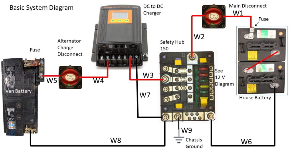
The wiring diagram for the system is just below, followed by a picture of the actual system built on a board for easy viewing of detail.
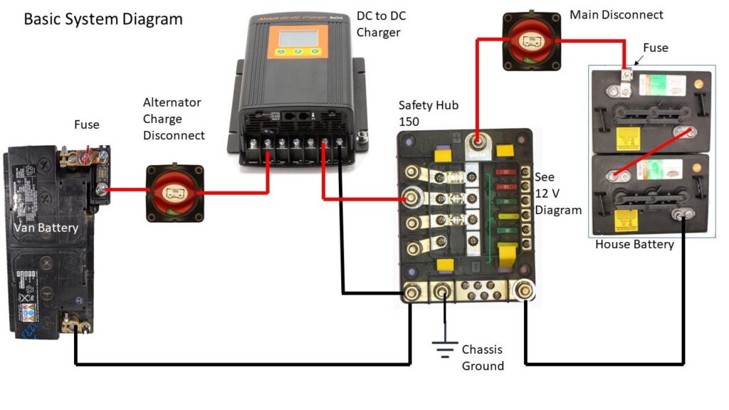
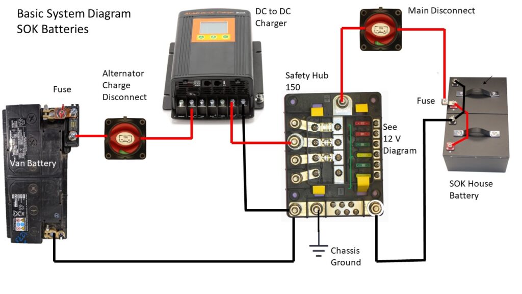
This thing is really simple – there are basically only 5 components and 9 wires! This is the golf cart battery version of the system.
The safety ground on the side of the DC to DC charger must be connected to the van chassis.
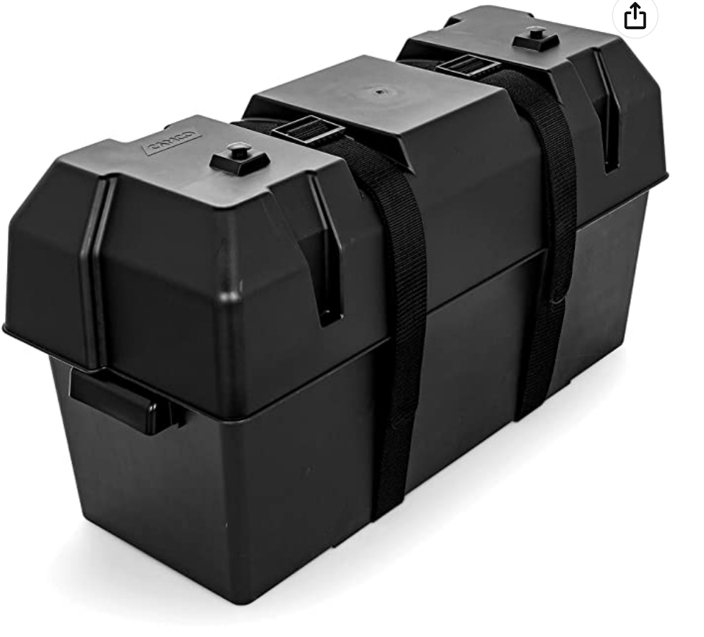
The version with LiFePo4 batteries is the same except that the batteries look like this – they are connected in parallel instead of in series…
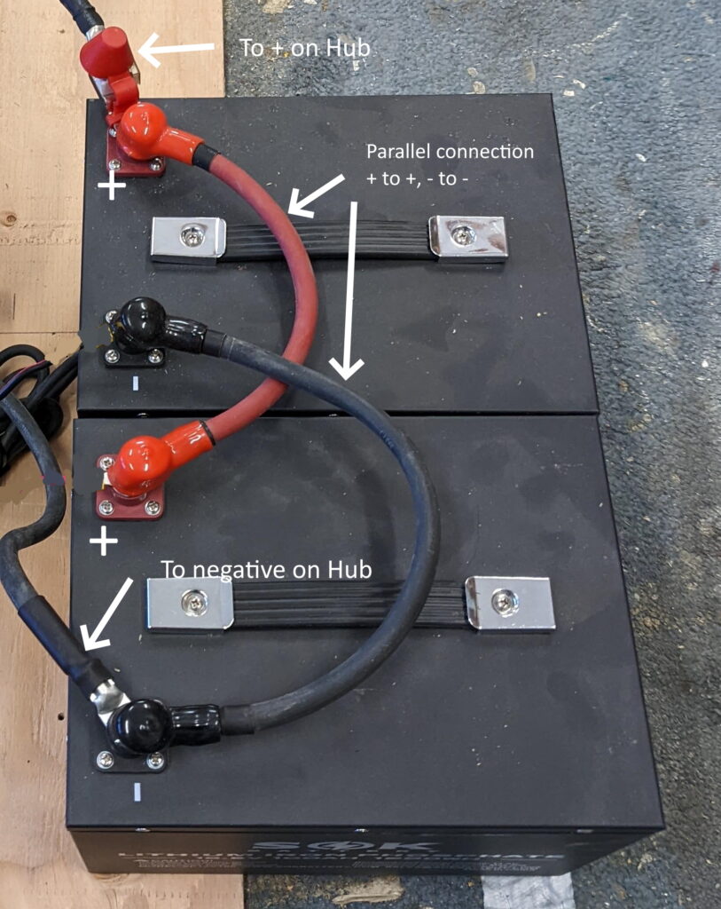
The only difference between the golf cart battery version and Li version is that the golf cart batteries are connected in series to make a 12 volt battery out of two 6 volt batteries, while the Li batteries are two 12 volt batteries hooked in parallel.
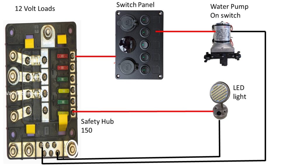
This diagram shows some sample 12 Volt loads hooked up to the low amperage loads side of the BlueSea Safety Hub 150. Examples of these low amperage loads would be the fridge, roof fan, furnace, lights … Basically any 12 volt load up to 30 amps. The actual 12 volt loads will depend on your van.
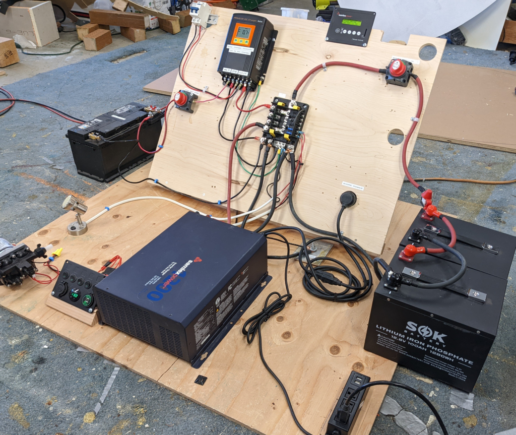
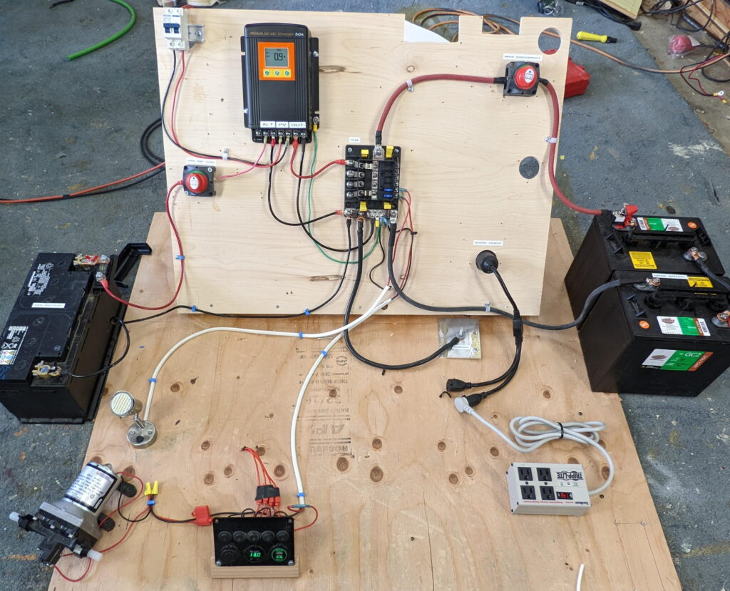
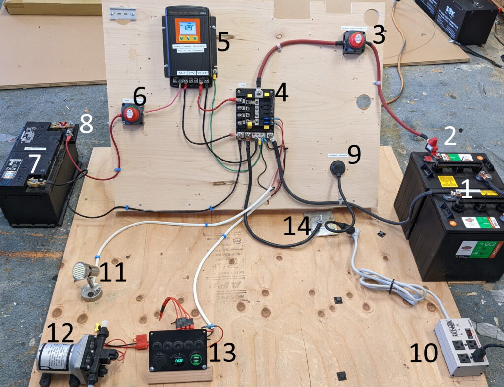
This picture shows the whole base system assembled and working on a model board with lots of space to show all the connections.

How it Works
Referring to the diagram above, the house battery on the right supplies current to the Hub in the center, which in turn distributes power to the house loads such as lights, pump, etc. The six 12 volt circuits on the right side of the Hub supply power to smaller loads like lights, fan, water pump, furnace… up to 30 amps each. A fuse is provided for each of these loads by the Hub. Larger loads can be connected to one of the four terminals on the left side of the Hub. The Hub provides a fuse for each of these terminals which can be up to 200 amps.
Charging of the house battery is from the van alternator/starter battery. The charging is controlled by the DC to DC charger to the left of the Hub. The DC to DC charger regulates the charging from the alternator and charges the house battery using the correct charging profile depending on the house battery type. This Kisae DC to DC charger also incorporates a Solar Charge Controller, which will make it easy to add solar later if desired.
Components List
This picture shows all of the components hooked up and ready to go. I did them on a model board in the shop to make it easier to see all the connections. Components are numbered to match table below. The table below provides the details on each of the components.
| Number | Name | Description | Cost | Lin | |
|---|---|---|---|---|---|
| Golf Cart Battery Alternative |
|||||
| 1 | House Battery Golf Cart Version |
Two 6 volt 210 Amp Hour golf cart batteries connected in series for 12 volts at 210 amp-hours. |
$190 | Costco | |
| Li Battery Alternative | |||||
| 1 | House Battery LiFePo4 Version |
Two SOK 12 volt 100 amp-hour LiFePo4 batteries connected in parallel. 200 amp-hours total |
$1140 | SOK battery | |
| 2 | Main Fuse | Battery terminal mounted fuse – 200 amp | $24 | Amazon | |
| 3 | Main Disconnect | Main disconnect switch. Cuts off all power. |
$14 | Amazon | |
| 4 | BlueSea Safety Hub 150 |
BlueSea Safety Hub provides busbars and fusing for all of the circuits | $112 | Amazon | |
| 5 | Kisae DMT 1250 | Kisae DC to DC charger and solar charge controller. It regulates charging of house battery from van alternator, and also from solar if you add solar. The DMT 1230 can also be used ($200) |
$250 | DonRowe | |
| 6 | Charging Disconnect | Switch to disconnect house battery from alternator charging. |
$14 | Amazon | |
| 7 | Van Starter Battery |
The van’s existing starter battery. This is the source of charging current to recharge the house battery. |
$0 | ||
| 8 | Fuse | Fuse at terminal of van battery 60 amp Details will depend on your van battery terminal. |
$14 | Victron | |
| 9 | Shore Power Connector |
Brings 120 VAC house power into the van when shore power is available. |
$23 | Amazon | |
| 10 | Plug Strip | Plug strip to connect to shore power. | $20 | Amazon | |
| 11 | LED light | There are many kinds of 12 volt LED lights available for vans – this is one example. |
$27 | Amazon | |
| 12 | Water Pump | There are many choices of 12 volt RV water pumps for vans – this is one example. |
$90 | Amazon | |
| 13 | 12 volt switch panel with USB Charging |
There are many types of switch panels with and w/o USB outlets available for vans – this is one example. |
$23 | Amazon | |
| 14 | Chassis Ground | Just showing the chassis ground to the van for some unknown reason. |
Installation Details
Lots of (hopefully) helpful details on installing the system in your van.
Layout
Get all the components together in the area of the van where you think you want to put the system.
Try various arrangements of the components considering the following factors.
- Place Batteries where they can be secured for crashes and accessed for maintenance and where they can be contained in their own box. Try to minimize the length of the wire runs from the batteries to the Hub.
- Place the disconnect switches where they can be accessed when needed.
- Keep wire runs for the heavy cables short to minimize voltage drop.
- Mount the Safety Hub 150 where you can access it to change fuses.
- The Safety Hub should have enough room and clearance to do the wiring.
You may also want to consider choosing a place where the runs out to your various 12 volt loads (lights, pump etc.) are easy to make. You may want to consider not locating all of your heavy weight items (batteries being one) on the same side of the van. Vans are pretty tolerant of more weight on one side than the other, but its best not to be extreme about this.
Allow space for other components that you want to add later, such as an inverter. The inverter is a heavy load with large cables that should be as short as possible.
Some components may have limits on the orientation they can be mounted in and may need spacing for ventilation requirements. If you plan to change to Li batteries later, allow a bit more room in the battery box as some of the Li batteries are larger than the golf cart batteries.
If you think you may want to add more battery capacity later, try to leave space for this next to the initial two batteries. From a battery to battery voltage drop standpoint, it is better if all the batteries are in the same place.
Once you have a good layout, you can trial mount the components and do a final check of all the factors above. At this point, you can measure the cable lengths and make the cables. Be careful to get the correct size lugs on each cable.
When you secure each of the components it is important to bear in mind that the attachments to the van should not only be good for day to day loads, but also in the event of a crash. You don’t want your DC to DC controller bonking you in the back of the head at 60 MPH because you did not attach it well!
If you need inspiration, there are lots of van electrical setups floating around the web – just bear in mind that a fair percentage are not very well thought out 🙂
Before you start to do any wiring, make sure that the battery is disconnected. The easiest way to do this is probably to remove the wire from the plus terminal of the battery – this should be done for both the van battery and the house battery.
Making or Buying Cables/Wires
You will need wires with lugs to connect the components together.
If possible, wait until you have all the components in hand and you can arrange them in their final positions – this will allow accurate measurements of wire lengths. When you measure the wire lengths, use the actual wire routing you will use, which might be longer than a direct connection to allow for supporting the wires or making them look a bit neater. Waiting to have the components in hand will also let you check the actual lug sizes.
This system does not have a lot of heavy cables, and many people will find that’s its easier and cheaper to have the cables custom made.
See this page for the options on making the cables yourself, or ordering custom made cable.
Installing the Batteries
The basic system uses either two golf cart batteries or two LiFePo4 batteries. In the case of the golf cart batteries, they are 6 volt batteries and hooked in series, and in the case of the Li batteries, they are 12 volt batteries and hooked in parallel.
The batteries should be mounted where they can be properly secured to the van and won’t break free in the case of a crash – locating them on the floor will be helpful for this. The location of the batteries should allow access (especially the golf cart batteries as they will need to have water added occasionally).
You should work out the layout for all of the electrical components in the system such that the wire runs are short. The batteries are best contained within a box that separates them from the other electrical components and prevents potential damage to other components from fumes. Lots of possibilities for doing this – for example enclose the batteries in the van furniture or use commercial battery cases. MDO plywood would make a very good case material. For the golf cart batteries, you may want to vent the battery box to the outside – see this page for the story on venting.
It’s also a good idea to make the batteries fairly easy to get out. There are a number of reasons you may need to get them out – some battery types even benefit from between taken out over hot summer idle periods.
Installing the Switches
High amperage switches are used to turn the system off by disconnecting the house battery from the system, and a 2nd switch to turn off charging from the van alternator/starter battery. Both switches should be located where they are accessible fairly easily.
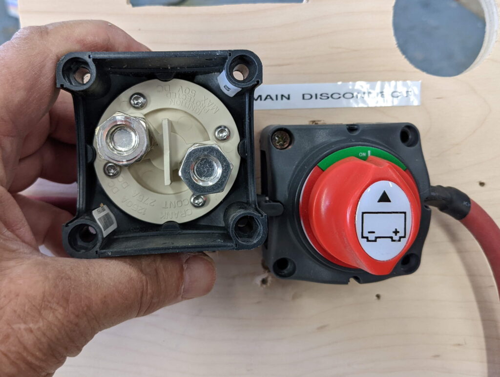
To wire the switches, remove the bottom to expose the terminals, remove a set of the plastic side panels to allow the wire to run into the switch. Remove the nut and washer from the two terminals, and place the 3/8 inch cable lugs over each terminal. Then place the washer over the terminal and tighten the nut tight. Replace the bottom plastic cover and then screw the switch in place.
Battery to Battery Charger
The Kisae DMT 1250 chosen for this project regulates the charging of the house battery from either the van alternator or solar panels. This unit does a carefully regulated multi stage charging of the house battery, and can be set for flooded lead acid batteries, AGM, or LiFePo4 Lithium batteries. This carefully regulated charging should result in longer house battery life and less chance of damaging the house battery due to incorrect charging. I picked Kisae because 1. the people who own them that I have talked to are happy with them; 2. it appears to be a carefully engineered product; 3. it handles lithium and lead batteries and the charging parameters can be changed; 4. they have a presence in Canada; and 5. they give prompt and very detailed technical support. In use and testing so far, it has performed well. But there are several of these kinds of units available from other vendors if the Kisae does not do it for you.
There is a cost saving alternative to this base system that uses a battery isolator instead of the battery to battery charger. This saves a couple hundred dollars, but has some limitations that should be considered.
- It is not recommended for LiFePo4 batteries – these batteries are expensive, and this investment should be protected with a full DC to DC charger. So, if you plan to use or upgrade later to Li batteries, you might as well go with the Battery to Battery charger right from the start.
- If you plan to add solar, you might as well buy the combined Kisae unit that does Battery to Battery charging as well as solar charging.
- Many newer vans have “Smart” alternators, and these will not work with a battery isolators – you must use the Battery to Battery charger.
See this page for details on using a battery isolator instead of a DC to DC charger…
Installing Shore Power
The base system includes a very simple shore power setup that will let you run 120 VAC (regular home power) when you are camping at a site that includes a shore power plugin.

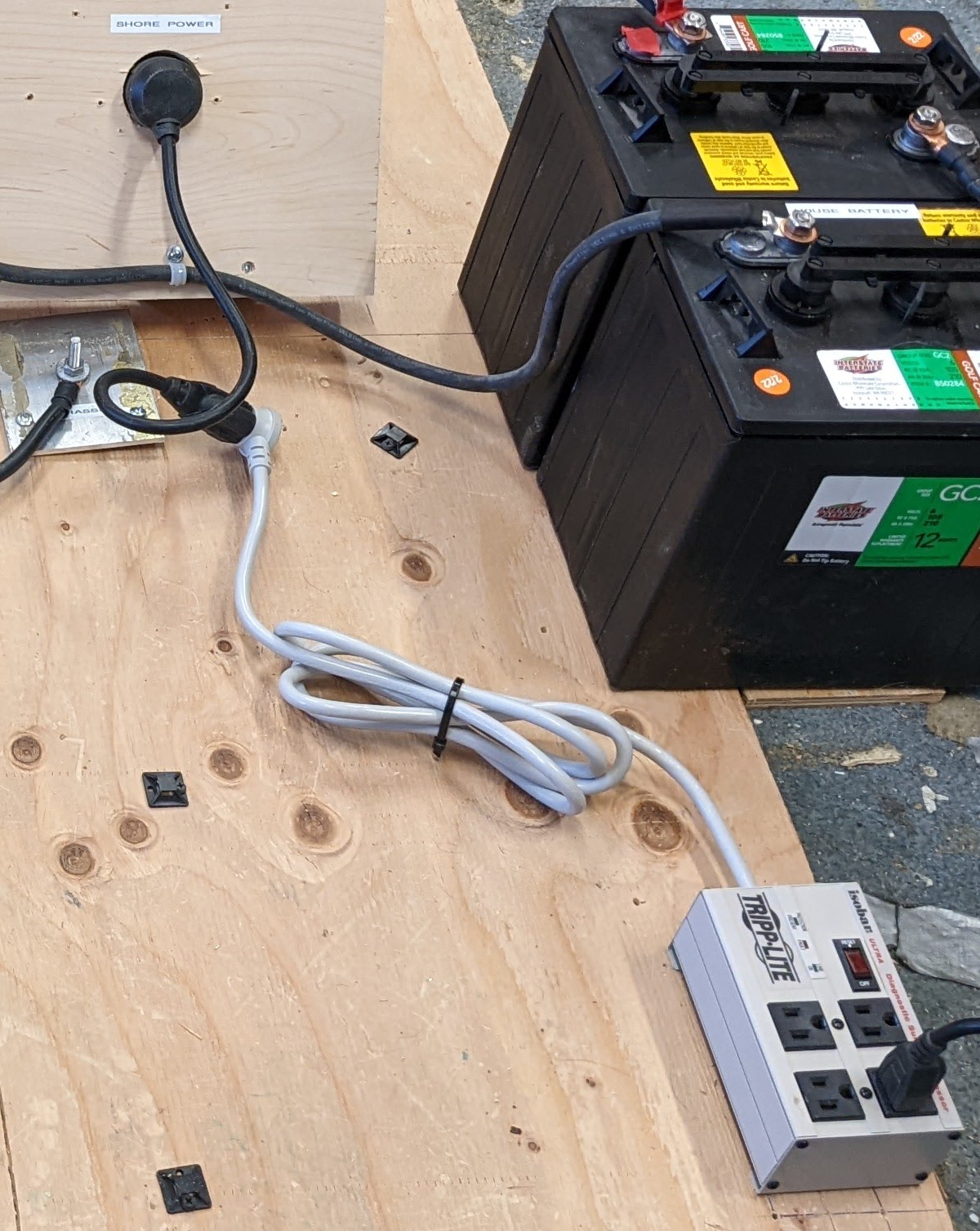
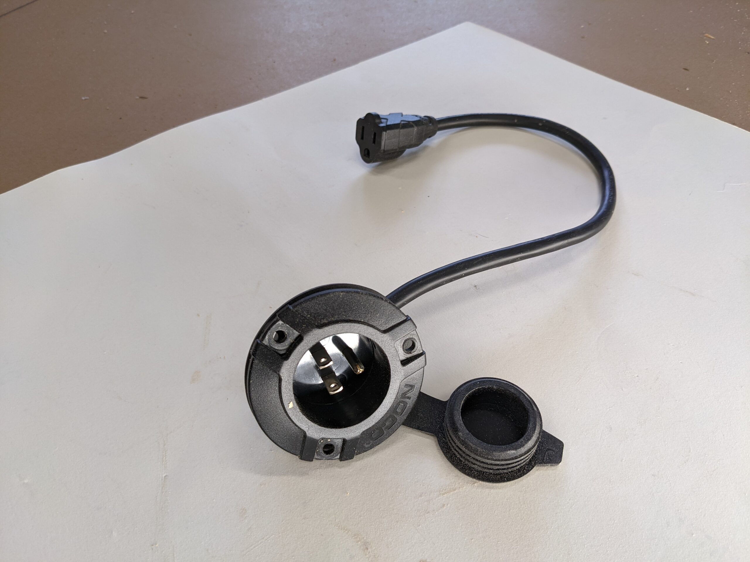
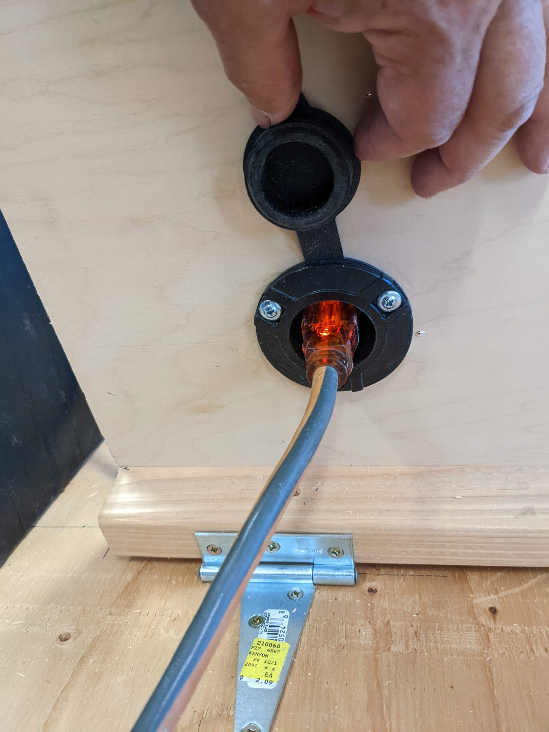
For twenty dollars and no wiring you get 120 VAC power to the inside of the van. This does require another hole in the van, but, at least on the ProMaster (and maybe others?), the hole can be in rear bumper plastic, so it’s pretty easy to manage. One forum member has used a hole in the floor for the shore power socket, which would be good for stealth vans.
On my first van conversion, I had a whole AC power system in the van with an AC distribution panel, several 120 VAC breakers, and outlets wired all over the van. This proved to be a total waste of time and effort – all we ever used was the one outlet near the galley. This simple system does just as well for us and saves space, time and money. I’ve heard the same comment from a number of people who put fancy AC systems in their van. Almost everything on a camper van runs on 12 volts, so, you probably don’t need 120 VAC outlets all over.
12 Volt Loads (lights, pump, …)
I don’t show a lot of detail on how to hook up the house 12 volt loads (lights, fan, water pump, furnace, fridge, …) as there is so much variation in which devices people will use and where they will put the devices.
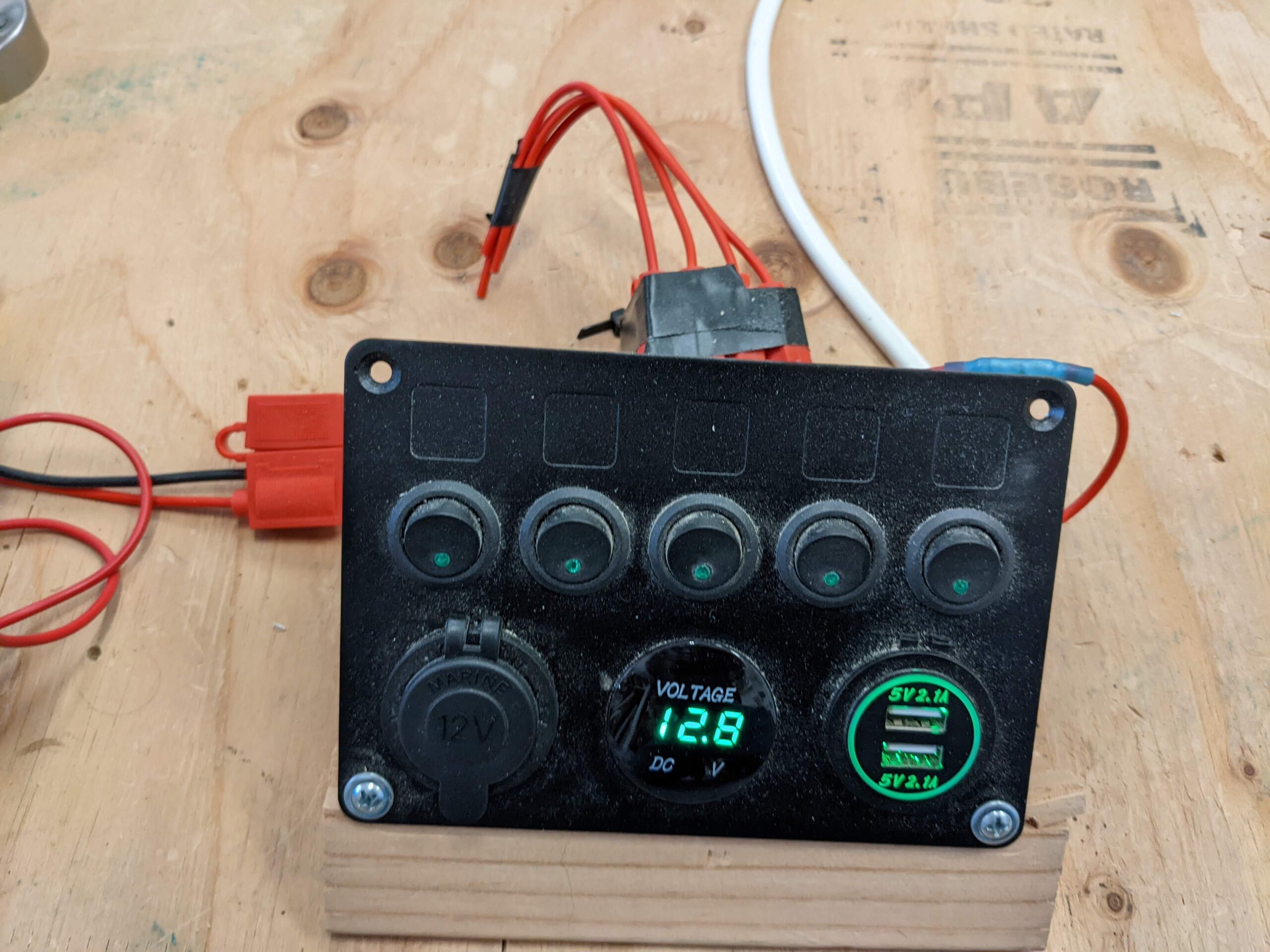
The BlueSea Safety Hub 150 provides six individually fused places to hook up these kinds of loads. If you try to dedicate one of these six circuits to each 12 volt device, you will likely run out of spaces. But there is no reason to do this – you can hook up multiple 12 volt loads to each of the six terminals. The sum of the loads on one circuit/fuse cannot be more than 30 amps as that is the largest fuse that can be used – since many of the 12volt loads are small, this is not be a problem. Another way to stretch the six slots is to use a switch panel similar to the one in the picture below. As a lot of the 12 volt house loads should or need to be on a switch and it can be nice to have all the switches on one place, these switch panels make a lot of sense to me. For this particular one, you can run a circuit/device off of each of the five switches. This one includes a fuse for each of the five circuits/switches. The only limitation is that the five circuits cannot add up to more than 30 amps simultaneous use. If you need more 12 volt circuits to work with, it’s easy to add one of these blade fuse boxes – this will provide 12 more 12 volt circuits, each with it’s own fuse. This approach also allows you to place blade fuse box in the best location for access and a good location for all the small 12 volt loads to come into. The blade fuse boxes are cheap and easy to install.
Wiring The System
See this page for information what kind of wire to use, and for wiring tools and techniques. And, to decide on making or buying the large cables.
Run by Run Wiring
High Amperage Runs:
The table below gives the data for each wire run, but see notes below for important exceptions.
| No | Gauge | lug 1 | lug 2 | Max length for 3% voltage drop |
| W1 | AWG 2 | 5/16 | 3/8 | W1 + W2 5 ft |
| W2 | AWG 2 | 3/8 | 5/16 | |
| W3 | AWG 6 | 5/16 | 1/4 | W3+W4+W5 10 ft |
| W4 | AWG 6 | 1/4 | 3/8 | |
| W5 | AWG 6 | 3/8 | Depends | |
| W6 | AWG 2 | 5/16 | 5/16 | 5 ft |
| W7 | AWG 6 | 1/4 | 5/16 | 10 ft |
| W8 | AWG 6 | 5/16 | Depends | 10 ft |
| W9 | AWG 2 |
5/16 | Depends | As short as practical |
Wires must be checked for two things: 1) That they will handle the current without overheating (ampacity), and 2) as the wire gets longer, that the voltage drop along the wire will not be excessive. More info on wire sizing here…
The wire gauges listed in the table above are sized to have sufficient ampacity for the load, and to have a voltage drop of 3% or less for the maximum length stated in the table.
Note 1: The gauges (#2) for W1, W2 and W6 allow for currents up to 200 amps as long as the length of the wire runs from the house battery to the Hub are 5 ft or less. If these runs are longer than 5 ft, then a larger gauge should be used to prevent voltage drop. The 200 amps is more than would be needed for the normal 12 volt loads (fridge, roof fan, furnace, pump, …), but designing for this excess current allows for an inverter up to about 1500 watts without increasing the wire gauge.
Note 2: The gauges (#6) for W3, W4, W5, W7 and W8 are based on charging current up to 50 amps (Kisae manual) and a one-way wire run length of 10 ft or less. If the distance is longer than 10 ft, then larger gauge wires must be used.
Low Current Runs:
These are the loads served by the low current side of the Hub and include things like lights, water pump, roof fan, furnace, and fridge. You could use the BlueSea Circuit Wizard to look at the wire run for each load and pick the lowest wire gauge that will for each one. This involves a bit of work and you will end up having to buy several different wire gauges. Instead of this, I recommend standardizing on #14 gauge. The #14 will be OK for most of the low current 12 volts loads, but the higher current ones that have long wire runs should be checked, and may require a larger gauge.
This table will give you rough idea how #14 gauge and #12 gauge do for several combinations of current and distance with a maximum voltage drop of 5%.
So, for example, a load that draws 10 amps and the one way length of the wire run is 12 ft, you would have to use 12 gauge wire as 11 ft is the maximum length for 14 gauge.
| Current (amps) | Maximum one way distance 14 gauge (ft) |
Maximum one way distance 12 gauge (ft) |
| 5 | 23 | 38 |
| 10 | 11 | 18 |
| 15 | 7 | 13 |
| 20 | 5 | 9 |
Be sure to mark each of the wires going out to 12 volt loads with what device it is powering. With so many wires coming in it is easy to lose track of where they come from.
Hooking up the 12 volt loads will likely be the most time consuming part of the wiring job. The Safety Hub terminal screws for the low current loads are pretty small and are close together, and you will probably find it necessary to hook two or three loads to some terminals as there probably won’t be enough terminals to have a dedicated terminal for each. This is one gadget that may make it easier. It grips the screw while you are trying to keep the wires in place and get the screw started – it sort frees up one hand to keep the wires in place while getting the screw started.
Another option would be to use spade style terminals rather than ring terminals. This way, you only have to loosen the terminal screw enough to slide the spade or spades under the screw head, and then tighten. This ABYC code advises against this in that if the screw loosens over time, the spade terminal can slide out, so, use your own judgement.
Bringing the system up
So, you are ready to see if it works!
Here are some steps you can go through the first time you fire it up…
- Make sure the batteries are disconnected from the system
- Using the diagrams, go over the whole system checking that all the wires are connected correctly – wire by wire by wire.
- As you go through wire by wire, give each wire a tug to make sure the lug is crimped OK
- Now check that the nuts on each terminal are tight – it’s so easy to just finger tighten a terminal and never come back to tighten it correctly
- Turn all of the loads that can be turned off off – so you won’t have everything coming on at once.
- You have had the main wire to the house battery plus terminal disconnected – now touch the wire to the house battery terminal briefly. Obviously if you see big sparks or smoke anywhere, pull the wire off and investigate. Note that if you have installed the inverter, you may get a spark when you touch main wire to the battery as the capacitors charge up.
- Tighten the main wire down to the house battery terminal. Look around for smoke or problems.
- If you have a volt meter in the system or a multi meter, check that the voltage is normal – i.e. 12 to 14 volts.
- Start turning loads on one by one. See that you get the intended effect – e.g. the light comes on. Check that none of the wires or terminals for that circuit get hot.
- Leave some of your highest amperage loads on for several minutes. Go around to every terminal in the system and touch it with you finger. Mostly the terminals should be slightly warm at the most. If you have some high amp loads (e.g. inverter), then these will get hotter, but not to the point of burning anything or melting plastic.
At this point, you are probably ready for a dry run just to see how things work overnight. Congratulations!!
If you use an IR temperature gun to look at temperatures, bear in mind that readings on bare metal terminals will not be accurate as the emissivity of the bare metal is low and won’t give good readings. You can use the IR gun to look at plastic or painted surfaces.
Gary 7/27/22
Hi Gary,
What size should the fuse be on the hub for the wire from the B2B charger (it’s labeled W3 on the diagram)?
Thanks,
Dave
Hi Dave,
As this charger is limited to 50 amps, a 50 or 60 amp fuse/breaker would be fine.
If you use a different DC to DC charger, than size if for your chargers maximum current.
The wire is sized for voltage drop and so is heaver gauge than 50 amps would require. Its sized for the voltage drop over the wires W3 plus W4 plus W5.
Gary
Hey Gary – you list W9 as AWG 6 wire but your picture seems to show it as AWG 2 (matching the size of the W1, W2, and W6 runs). My assumption would be that the chassis ground from the safety hub should be the same size as the cables running to it from the house battery (aka your table should be updated to make it AWG 2) – what do you think?
Hi Mike,
The W9 wire normally does not carry any current at all because all the current is carried by the W2 and W6 wires and a lot of systems are wired with a smaller gauge wire for the chassis ground. If you wire any of your loads using the chassis as the return path (ie only run a +12volt wire to the load), then the W9 wire does complete the circuit back to the battery negative, but I recommend that people always use a full size return wire from every load, so the W9 wire would not carry any current.
But, on further checking, the ABYC marine code requires that the chassis ground wire has to be no more than one wire size smaller than the largest wires to the loads. The thinking behind this is that if there is a short to to the chassis from one of the large +12 volt wires (eg the W2), that the chassis ground wire(W9) has to be large enough to carry enough current back to the battery to blow the fuse in the load wire. So, I’m going to change change it to #2 as you suggested – it could technically be one size smaller, but I don’t think anyone will want to order another size wire just for this.
Thanks for pointing this out!
Gary
Gary – I appreciate the quick and thorough response. Your website has been a gold mine for me in my planning of a simple electrical system, and I really appreciate how clearly and thoughtfully you lay everything out.
Hey Gary,
Looks like you have two grounds; are there any issues with that? W8 should be a ground since the van battery is grounded to the chassis. If W8 is a “big enough” cable then would W9 be redundant?
Great layout and great learning tool. Thanks for putting this out there. I’m working on a similar basic system with the Safety Hub.
Thanks,
Dave
Hi DAve,
I’d love to get get some pictures on your new system when you get done.
The W8 wire is actually the return wire for the run to the van battery and carries the return current from when alternator charging is going on.
The W9 line connects the negative side of the system to the chassis. One thing it does is insure that if there is a short to the chassis from a positive wire or other positively charged source, that it will draw current and blow the fuse on that circuit.
Its OK to have multiple connections to ground (to the chassis) – for example, if you added an inverter to the basic system, it will probably have its own ground terminal that needs to be connected to the chassis.
Gary
Hi Gary,
I am considering two changes to my van. Changing the current controller to the Kisea DMT1250 and changing the two 5 year old 6v golf cart batteries for one SOK 206Ah lithium. One big plus to the Kisea is the dual charging ability which I currently do not have, only the 290w solar on the roof. I have a Blue Sea Systems ST Blade ATO/ATC Fuse Block currently in our camper van. I see with the use of the BlueSea Safety Hub 150 you have AW6 wire going from the negative of the starter battery to that hub. Since both the starter battery and the hub are grounded to the chassis I am wondering if I will need to add that wire, and if it is okay to do so to my current fuse block, or if it would be advisable to switch to the safety hub.
Thanks,
David
Hi David,
I think that the normal way to do that on a system without the Safety Hub 150 would be to run a wire from the starter battery negative to your negative busbar or directly to the negative terminal of the house battery. If both the van battery and house battery are grounded to the chassis, then you can use the chassis as the return path instead of a dedicated return wire. I’m not a fan of doing this as over time you tend get corrosion at the chassis connections and this results in problems that can be hard to find.
I’d keep the BlusSea fuse box you have – it supports more 12 volt circuits than the one that is included in the Safety Hub 150 and it should be fine. But, the negative line from the van battery should connect to the house battery negative and not the BlueSea fuse box negative – the BlusSea fuse box is only designed to take small DC loads.
The 206 AH SOK looks like a good choice, but it is limited to 100 amps discharge current, so, that would limit your ability to run things like an inverter. An advantage of using two 100 AH in parallel is that they both have 100 amp max current limits, so you get a 200 amp max current limit.
I just noticed visiting the SOK site that they have a new version of the 100 AH battery that has a built in heater for getting the battery warm enough in cold weather to be able to charge it, and they have added Blue tooth to the BMS. Interesting new features.
Gary
Gary,
Thanks for the help and info. I am going to go ahead with the changes. I have the Kisae 1250 arriving today from Don Rowe (really prompt service by the way) and I’ve ordered two of the SOK 100’s (without Bluetooth) from Current Connected. Part of my thinking on the non-Bluetooth SOKs is I have the Victron BMV700 that has worked well with the FLA batteries. Probably won’t give me all the info the Bluetooth SOK could but hopefully it would be info that is not critical. One of the things I am concerned about though is the Victron shunt needing “everything” on the negative side to go through the shunt. I believe that would mean that the shunt should go in W6 in the above illustration. Would I then want to move the chassis ground from W9 to the battery negative. Any other thoughts on the subject I would be happy to hear.
David
Hi David,
Good choices I think.
I also use the Victron Battery monitor.
I believe that you are OK if you just put the shunt in the W6 line in that it is the only path to the negative terminal of the battery.
Please let me know how the system comes out – a picture would be great.
Gary