 This section goes over the design of the electrical system for the camper conversion, the selection of components, and the installation.
Back to the ProMaster camper van conversion main page…
This section goes over the design of the electrical system for the camper conversion, the selection of components, and the installation.
Back to the ProMaster camper van conversion main page…
| Safety Warning and Disclaimer |
There are serious safety issues involved with wiring your own system. The voltages are high, and potentially lethal. Doing the system incorrectly can lead to serious consequences down the road.
PV systems have the added hazard that even when the grid power is turned off, the system can be “live” and present a serious shock hazard.
If you don’t feel like you want to put in the time to learn how to do this correctly, then find an electrician that you can partner with to do this part.
I want to make it very clear that I am not an electrician, and I take no responsibility whatever for the correctness of the wiring hints below — you need to do your own homework!
http://www.builditsolar.com/Contact/legal.htm
Overview
We do not want to be tied to electrical hookups at RV parks, so we incorporated a good sized house battery and tried to minimize our electrical loads. Most of our loads are DC and run directly off the house battery with only a couple of modest AC loads that can be powered either by our onboard inverter or shore power. The house battery can be charged from the van alternator, or from a large solar panel on the roof, or from shore power if available. The battery can supply a couple of days (or more) with typical loads, and on a sunny day, the solar panel is sized to fully recharge a depleted house battery. At this point (Jan 2017) we have used our van for about 2 years and the electrical system has performed well without any significant problems. 2019 Update: Our 2014 ProMaster van now has 70K plus miles on it with many trips. The electrical system has performed well, and no significant changes have been needed. We did add a Victron Battery Monitoring system just to have better visibility of how the batteries are doing — a nice gadget to have, but definitely not a necessity.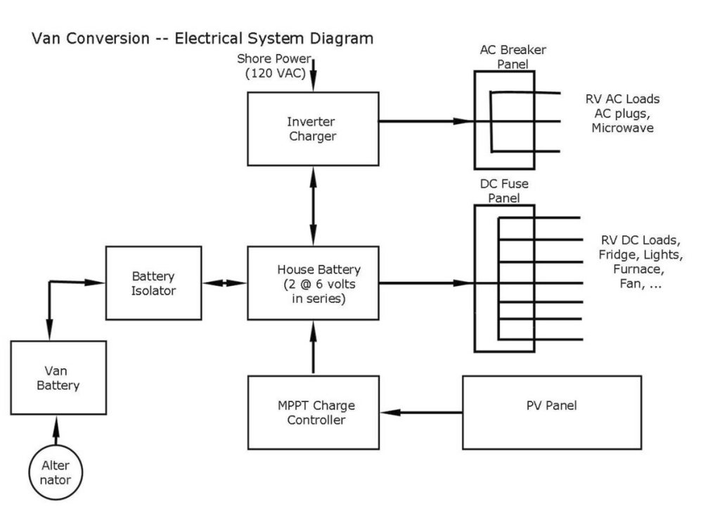 At the heart of the camper electrical system is the house battery. It can receive charge from three separate sources: 1) the van alternator when the engine is running, 2) the roof mounted solar panel, and 3) the inverter/charger when plugged in to shore power.
The house battery powers all of the DC loads (like lights, fridge, furnace fan, water pump) via the DC distribution panel. It also powers an inverter to provide 120 Volt AC house power to our small number of AC loads. Most of the electrical devices on the van run directly from the 12 volt house battery.
The Battery Isolator prevents the RV loads from running down the van starting battery, the PV panel charges the house battery via the Charge Controller, the DC and AC distribution panel safely distributes power to the RV electrical loads, the Inverter/Charger supplies 120 AC power from the house battery and also charges the house battery when hooked up to shore power.
All of this explained in much more detail below.
At the heart of the camper electrical system is the house battery. It can receive charge from three separate sources: 1) the van alternator when the engine is running, 2) the roof mounted solar panel, and 3) the inverter/charger when plugged in to shore power.
The house battery powers all of the DC loads (like lights, fridge, furnace fan, water pump) via the DC distribution panel. It also powers an inverter to provide 120 Volt AC house power to our small number of AC loads. Most of the electrical devices on the van run directly from the 12 volt house battery.
The Battery Isolator prevents the RV loads from running down the van starting battery, the PV panel charges the house battery via the Charge Controller, the DC and AC distribution panel safely distributes power to the RV electrical loads, the Inverter/Charger supplies 120 AC power from the house battery and also charges the house battery when hooked up to shore power.
All of this explained in much more detail below.
Components:
These are our choices for the main components.
Item Description Cost House Battery 2 @ 6 volt, 200 AH golf cart batteries (Costco) $180 Inverter/Charger Triplite APS 1250 Inverter/Charger $406 Battery Isolator PAC-200 Battery Isolator 200 amp $46 MPPT Charge Controller Midnite Solar KID Charge Controller $280 AC/DC Distribution Panel PD5000 AC/DC Power Control Panel $58 PV Panel SolarWorld SW315 PV panel $368 Total (not including fuses, wire, …) $1338
Batteries
We used two 220 amp-hr, 6 volt golf cart batteries from Costco connected in series for 12 volts. This gives us some reserve for cloudy days.. We thought about using an AGM battery, the advantages of the AGM battery is that it does not need water to be added (low maintenance), it vents less hydrogen during charging than a flooded battery, and there is no chance of spillage.. On the down side, they are quite a bit more expensive for the same capacity, and appear (from the Trojan Battery data below) to have a shorter life. The conventional flooded lead-acid golf cart batteries we used are less expensive and very readily available, but will require checking the water levels from time to time, and the battery compartment will have to be vented to the outside to prevent hydrogen buildup. But, flooded batteries vent very little hydrogen when charged at the correct rate. Just as an approximate comparison — some data on two of Trojan Batteries offerings of flooded and AGM batteries.| Type | Model | Volts | amp-hr (20hr) | Len | Wid | Ht | weight | Cycles (80% discharge) | Cost/bat | |
|---|---|---|---|---|---|---|---|---|---|---|
| Flooded | T-105 | 6 | 225 | 10.3 | 7.11 | 11.07 | 62 | 750 | $110 | |
| AGM | 6V-AGM | 6 | 200 | 10.3 | 7.08 | 10.74 | 65 | 500 | $295 | |
AC and DC Distribution and Fuse Panel
After quite a bit of looking around, I found this nice and not very expensive distribution panel for RV’s that handles both the AC and DC distribution in one fairly compact package. It provides for up to 12 DC circuits and up to 4 AC circuits.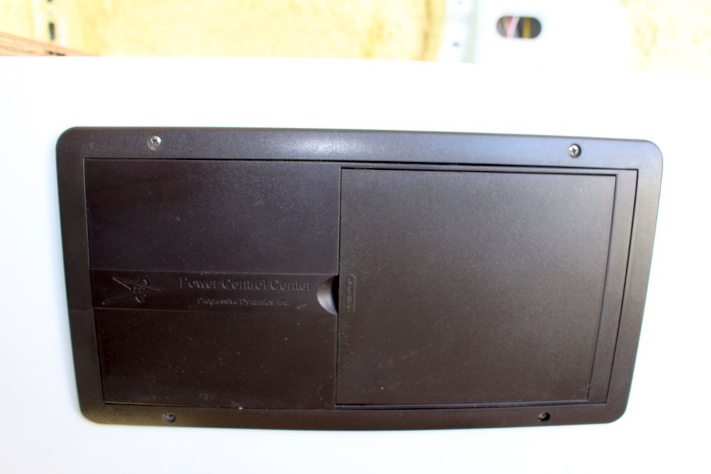 This looks like another good option for a combined AC and DC distribution panel…
Battery Isolator
This gadget allows the van alternator to be used to charge the house battery, while preventing the van starting battery from being drained by powering loads in the RV. It isolates the van starting battery from the house battery when the ignition switch is off so that RV loads only discharge the house battery. The idea is that even if you discharge the house battery overnight, the van starting battery will still be fully charged.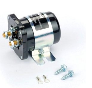 This relay based unit appeals to me because: 1) it does not have the voltage drop that the diode based isolators do, 2) it does not get wired between the alternator and the starting battery as the diode ones do (so less interference with the van wiring), and 3) It is easy to hook up because it just needs a wire from the starting battery and an 12V source that goes on with the ignition switch.
Not sure if I’m reading this right, but it seems like when you start the van that this unit puts the starter battery in parallel with the house battery. I guess this could be good if your starting battery is low, but maybe not so good if your house battery is low?
In hindsight, a unit with a lower amperage rating would have been fine. The unit is inline with a 50 amp circuit breaker, so anything over 50 amps would probably be fine. The maximum recommended charging current for the golf cart batteries is about 30 amps.
Another option would be to use a Voltage Sensing Relay. This is a relay similar to the one above, but the relay is activated just monitoring the van battery voltage to determine if the engine is running or not. It requires less wiring.
This relay based unit appeals to me because: 1) it does not have the voltage drop that the diode based isolators do, 2) it does not get wired between the alternator and the starting battery as the diode ones do (so less interference with the van wiring), and 3) It is easy to hook up because it just needs a wire from the starting battery and an 12V source that goes on with the ignition switch.
Not sure if I’m reading this right, but it seems like when you start the van that this unit puts the starter battery in parallel with the house battery. I guess this could be good if your starting battery is low, but maybe not so good if your house battery is low?
In hindsight, a unit with a lower amperage rating would have been fine. The unit is inline with a 50 amp circuit breaker, so anything over 50 amps would probably be fine. The maximum recommended charging current for the golf cart batteries is about 30 amps.
Another option would be to use a Voltage Sensing Relay. This is a relay similar to the one above, but the relay is activated just monitoring the van battery voltage to determine if the engine is running or not. It requires less wiring.
Inverter/Charger:
The inverter/charger performs two jobs. When you are not hooked up to shore power and are being powered by the house battery, it provides limited 120 volt AC power for the van from the house battery. When you are hooked up to shore power, it turns off the inverter function and passes the shore power through to the AC loads that are connected to the inverter, AND it charges the house battery using a full 3 stage charger. We selected the Tripp Lite APS1250, which provides 1250 watts of AC from the battery, and when in charger mode, provides up to 30 amps of battery charging using a 3 stage charger.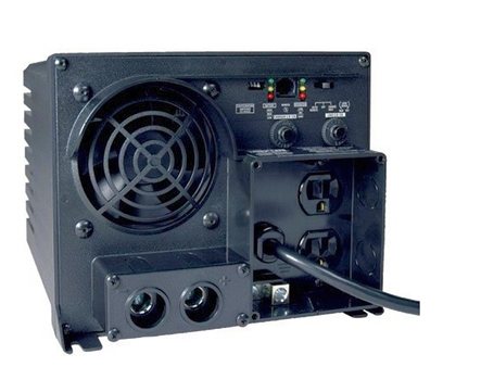 These inverter chargers are made by several companies. I chose the Tripp Lite mostly because I have a larger one I bought several years ago and it has held up well.
I like this kind of inverter/charger because: 1) it eliminates the need for a separate battery charger to charge from shore power, 2) it has 3 stage charging, so its easy on the battery, 3) it automatically switches from the inverter powering AC loads to the shore power when you plug into shore power, so you can hook your AC loads up to the inverter and they will be powered whether you are on shore power or on house battery power.
Like most of these inverters, it draws some power from the battery whenever the inverter is turned on even if nothing is plugged into the inverter, but it can easily be turned off manually when no AC power is being used, so this is a nuisance, but not a serious one.
Update 1/1/2016: One thing I’ve noticed is that pure sine wave inverter/chargers have dropped in price some, so if you plan to run AC loads that might need the pure sine wave output, you might want to upgrade to a pure sine wave inverter — one example is the Xantrex Freedom HFS 2000 Inveter Charger.
These inverter chargers are made by several companies. I chose the Tripp Lite mostly because I have a larger one I bought several years ago and it has held up well.
I like this kind of inverter/charger because: 1) it eliminates the need for a separate battery charger to charge from shore power, 2) it has 3 stage charging, so its easy on the battery, 3) it automatically switches from the inverter powering AC loads to the shore power when you plug into shore power, so you can hook your AC loads up to the inverter and they will be powered whether you are on shore power or on house battery power.
Like most of these inverters, it draws some power from the battery whenever the inverter is turned on even if nothing is plugged into the inverter, but it can easily be turned off manually when no AC power is being used, so this is a nuisance, but not a serious one.
Update 1/1/2016: One thing I’ve noticed is that pure sine wave inverter/chargers have dropped in price some, so if you plan to run AC loads that might need the pure sine wave output, you might want to upgrade to a pure sine wave inverter — one example is the Xantrex Freedom HFS 2000 Inveter Charger.
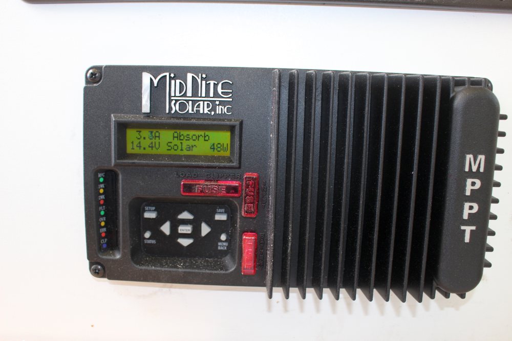
Solar Charge Controller:
The charge controller goes between the PV panel and the house battery. It transforms the PV panel output voltage down to a voltage that is suitable for charging the battery, and it prevents the solar panel from overcharging and damaging the battery. I am using the MinNite Solar KID charge controller. This is a relatively new design that has quite a bit of flexibility for small solar systems. It includes MPPT (Maximum Power Point Tracking) which is more efficient than the PWM models. The unit is very nicely made in the US. The manual is written in an informative and down to earth style that is refreshing compared to the awful manuals that come with so many products. I’m told the phone tech support is very good. The unit includes basic monitoring of the system, and they sell an add on unit for more extensive monitoring if desired. Midnite Solar has a nice online tool that lets you see if the PV panel(s) you are planning to use are compatible with the KID. Price is about $285.Update: March 4, 2015: They have just raised the price up to $440. I think that this is kind of steep, and I’d probably look for a better option. Further update: see the comment by Dennis below for a less expensive Victron option.
PV Panel:
I decided to use just one large solar panel. This seems easier than mounting and wiring together several panels. The panel I selected the SW315 from Solar World. Its a 315 watt, 72 cell panel. The 72 cell design provides enough voltage (36 volts) to work with the KID charge controller as a single panel. I ordered the panel from the local Platt Electric — their price was competitive and if you pick it up at Platt there is no shipping charge. With a little discount they gave, it came to $368 — about $1.17 per peak watt.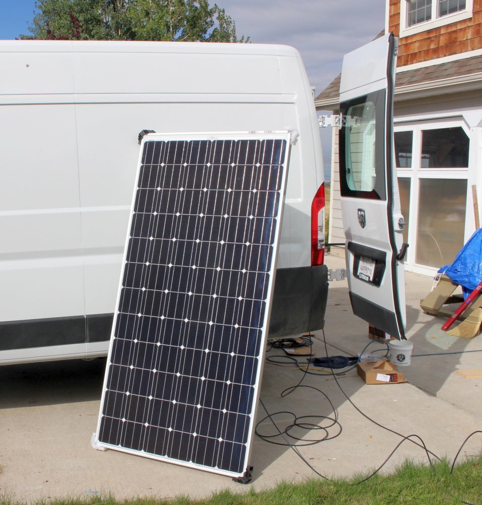 I have not mounted the panel yet. Thinking about mounting it as low as possible and aft of the Maxx Fan on the centerline of the roof.
Still thinking about the best way to bring the two wires from the PV panel into the van. I’m wondering if I can bring them through the backup camera housing?
I have not mounted the panel yet. Thinking about mounting it as low as possible and aft of the Maxx Fan on the centerline of the roof.
Still thinking about the best way to bring the two wires from the PV panel into the van. I’m wondering if I can bring them through the backup camera housing?
Update: August 2015: Solar panel mounted …
Update: Full details on the solar panel mounting and wiring here…
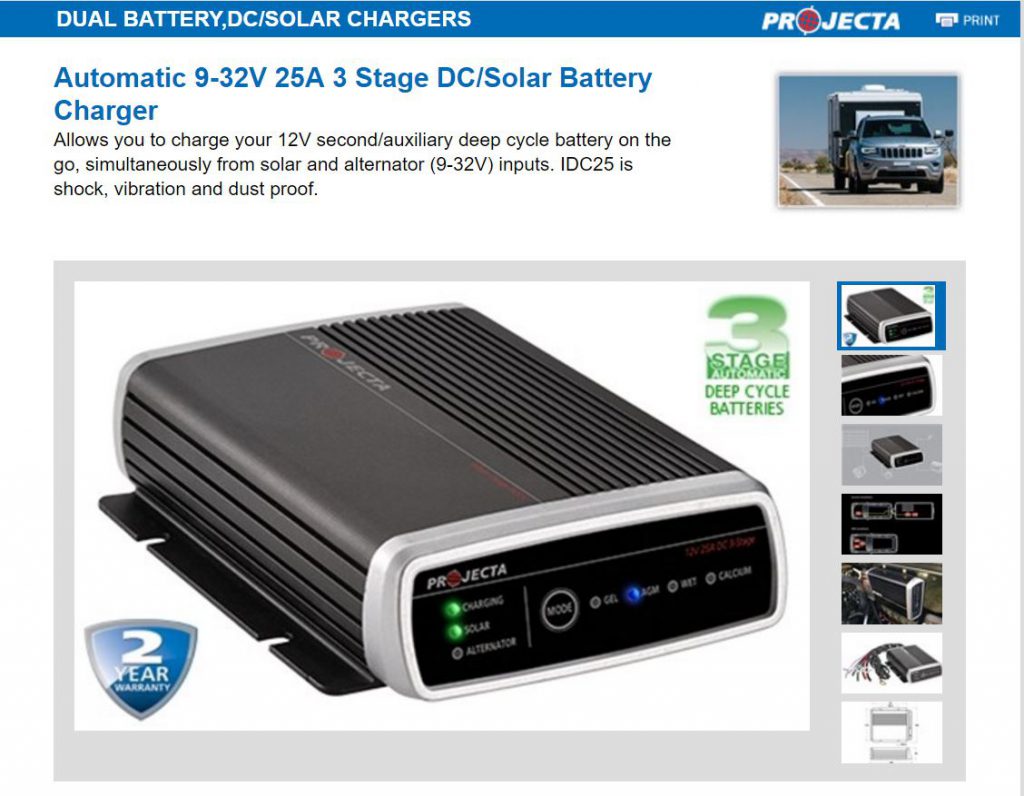
Update: March 2017 – new product to look at
Ran across this house battery charger. It will charge from the van alternator or solar (or both at same time). Its a full three stage charger that will charge the house battery optimally regardless of the alternator output voltage or solar panel voltage. It has charge profiles for all the common lead-acid batteries. The solar charger accepts only 12 volt PV panels, but it is an MPPT charger. It appears to be a new product, but definitely worth a look.
Wire:
For most of the DC and AC circuits, I used regular 14 gage Romex house wire. I used nearly all of one 250 coil. There are a couple runs that use 12 gage Romex due to higher demand and/or to reduce voltage drop. I’m aware that some sources recommend using stranded wire for greater vibration resistance, but the Romex is widely used in RV’s and does not appear to cause an problems. The outer plastic protective sheathing and its wide availability at low cost are pluses.Choosing wire type:
There is an ongoing (never ending:) discussion of solid vs stranded wire for RVs. In a nutshell, some believe that solid wire (eg Romex) is subject failure under high vibration conditions. On the other hand, its easy to work with, has the protective outer jacket, is inexpensive, is used in a lot of commercial RVs, and is built to a spec for consistent quality. I have not been able to find any accounts of actual failures of Romex due to vibration in actual RV service.
Stranded wire is said to be more vibration resistant, but is more susceptible to corrosion, and is more expensive.
If you decide to go with stranded wire, there are many choices. I thing this type of boat wire would be a good choice. It meets ABYC and Coast Guard standards, is tinned for better corrosion resistance, and has an outer jacket for better protection and easier routing. Its more expensive than Romex, but probably not a major expense in the context of total conversion cost. I would make sure that you get wire that is manufactured to a standard, and that the standard makes sense for use in RVs. Doing things like cutting the ends off cheap China extension cords to make RV wires seems like asking for trouble to me.
There were a few places where larger gage stranded THHN wire was used (e.g. between inverter and battery and between van and house battery). I got this all at Lowes where they will cut pieces to the length you want. A good way to go for picking wire gage is to use the BlueSea Circuit Wizard calculator. It uses the ABYC (American Boat and Yacht Council) boat wiring standards to size wires, which should be a good fit for RVs. It has inputs for voltage drop, multiple conductors bundled, load duration, and insulation temperature rating — be sure to examine all the inputs. The calculator is easy to use, and requires very little electrical knowledge to use successfully.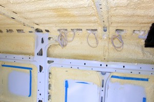
Circuits
While the overall wiring diagram for the whole system gets a bit busy (and more than I am up to drawing), it really consists of a few simple functions that are largely independent of each other. This section goes through the details of each of the functions, which are:- House battery charging from the van alternator
- House battery charging from the solar panel
- Satisfying 12 volt DC loads (DC distribution panel)
- Satisfying 120 volt AC loads and Shore Power
House Battery Charging from Van Alternator
This is the electrical subsystem responsible for charging the house battery from the van alternator when the van is running.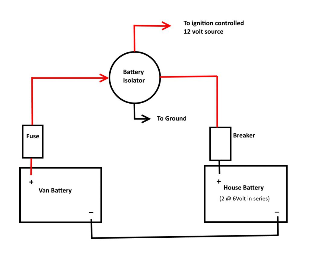 When the van engine is running, the relay closes allowing the van battery/alternator to charge the house battery.
The battery isolator relay connects the van battery to the house battery only when the van ignition switch is on. This prevents house loads from discharging the the van battery and resulting in a vehicle that has a flat battery in the morning and won’t start.
The barratry isolator relay is turned on by connecting it to a 12 volt power source on the van that is only on when the ignition switch is on. I used power from the 12VDC outlet near the driver side back door as it is only powered when the ignition is on. I ran a 14 gage wire from the 12 VDC power socket to the battery isolator. The other relay terminal on the battery isolator is hooked to any handy ground. The isolator I used is a PAC-200 (see above) — the 200 amp rating is quite a bit more than is required.
The 50 amp DC circuit breaker protects the wire between the van and house batteries. The circuit breaker can also be manually switched off, so it acts as a disconnect when you want to be sure there is no connection between the van and house batteries. The breaker is sized to be a bit above the maximum recommended charging current for our batteries so that if the breaker trips we will know the battery is being charged at too high a rate. The maximum recommended charging rate flooded lead acid batteries is in the range of C/10 to C/5 (where C is the capacity of the battery in amp-hrs), so about 33 amps for our batteries.
The van alternator is the source of power for both charging the van battery and the house battery.
The wires between the house and van battery are 8 gage — this provides the 50 ampacity with less than 2% voltage drop for the about 10 ft run.
When the van engine is running, the relay closes allowing the van battery/alternator to charge the house battery.
The battery isolator relay connects the van battery to the house battery only when the van ignition switch is on. This prevents house loads from discharging the the van battery and resulting in a vehicle that has a flat battery in the morning and won’t start.
The barratry isolator relay is turned on by connecting it to a 12 volt power source on the van that is only on when the ignition switch is on. I used power from the 12VDC outlet near the driver side back door as it is only powered when the ignition is on. I ran a 14 gage wire from the 12 VDC power socket to the battery isolator. The other relay terminal on the battery isolator is hooked to any handy ground. The isolator I used is a PAC-200 (see above) — the 200 amp rating is quite a bit more than is required.
The 50 amp DC circuit breaker protects the wire between the van and house batteries. The circuit breaker can also be manually switched off, so it acts as a disconnect when you want to be sure there is no connection between the van and house batteries. The breaker is sized to be a bit above the maximum recommended charging current for our batteries so that if the breaker trips we will know the battery is being charged at too high a rate. The maximum recommended charging rate flooded lead acid batteries is in the range of C/10 to C/5 (where C is the capacity of the battery in amp-hrs), so about 33 amps for our batteries.
The van alternator is the source of power for both charging the van battery and the house battery.
The wires between the house and van battery are 8 gage — this provides the 50 ampacity with less than 2% voltage drop for the about 10 ft run.
Battery Charging from Solar Panel
This is the part of the electrical system that charges the house battery using a roof mounted PV panel.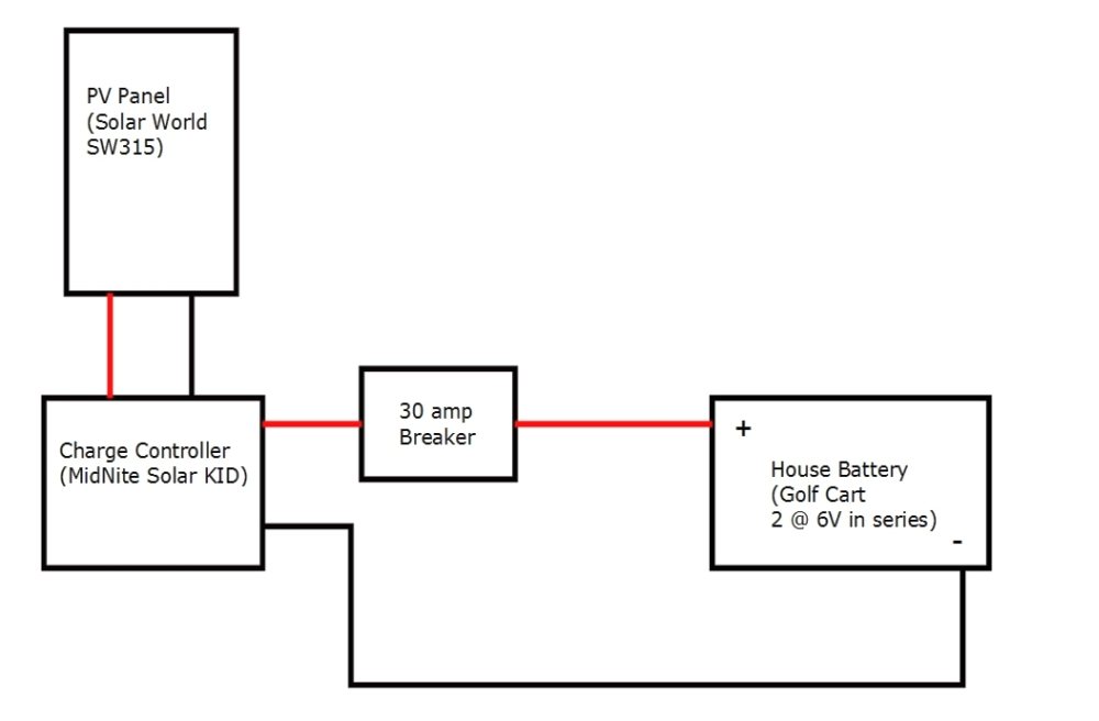
Satisfying 12 Volt DC Loads
This is the part of the electrical system responsible to safely supplying power to the campers 12 volt load: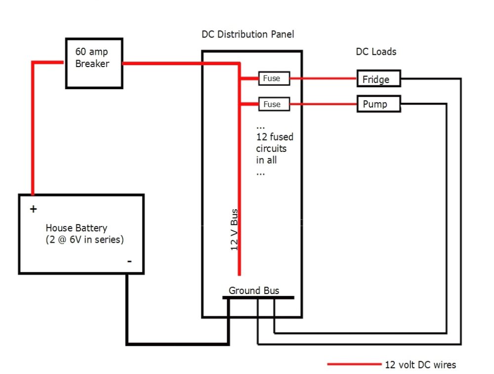
Satisfying 120 Volt AC Loads and Shore Power Battery Charging
This part of the electrical system is responsible for distributing power to the 120 VAC loads in the camper, and also manages whether the source of the AC power is shore power or the camper inverter. It also covers charging the house battery from shore power.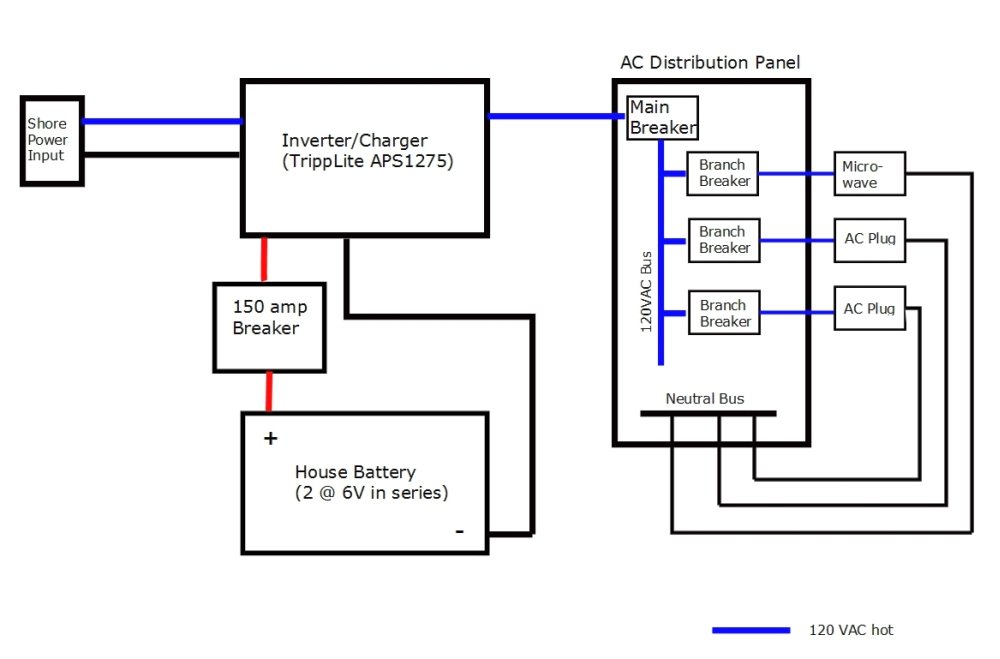
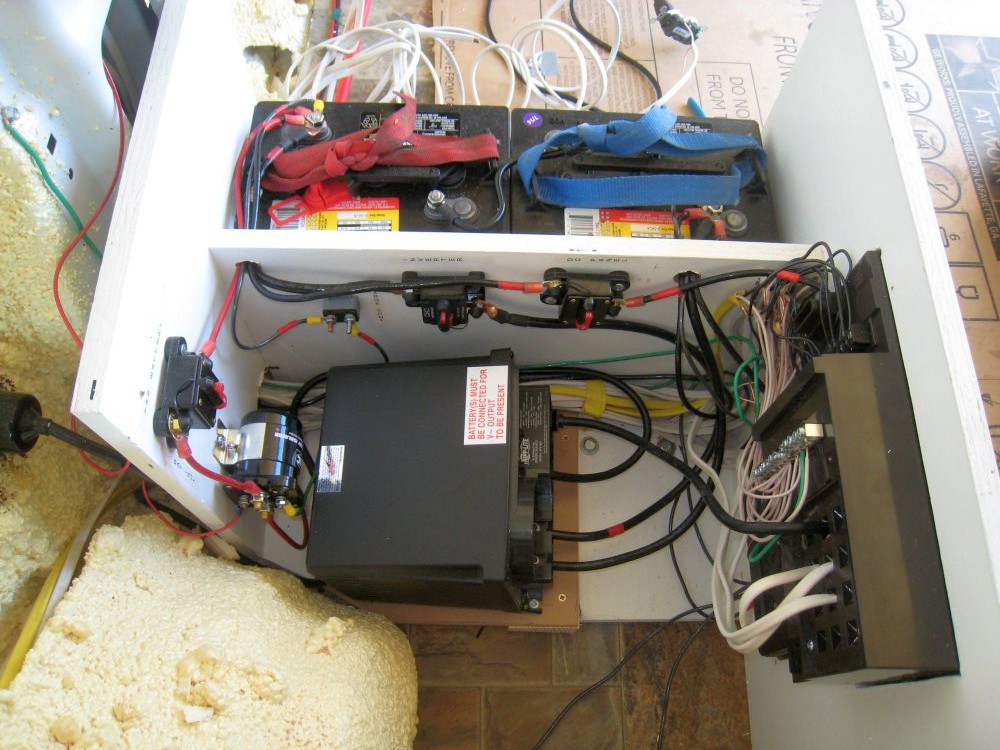
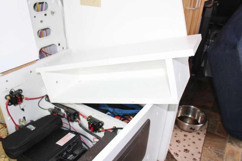
Installation
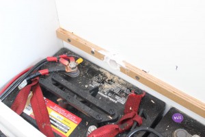
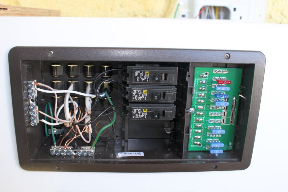
This section provides some pictures showing how I installed the components in our van. The batteries plus all the main components take up an about 2 by 2 ft space under the bed on the drivers side.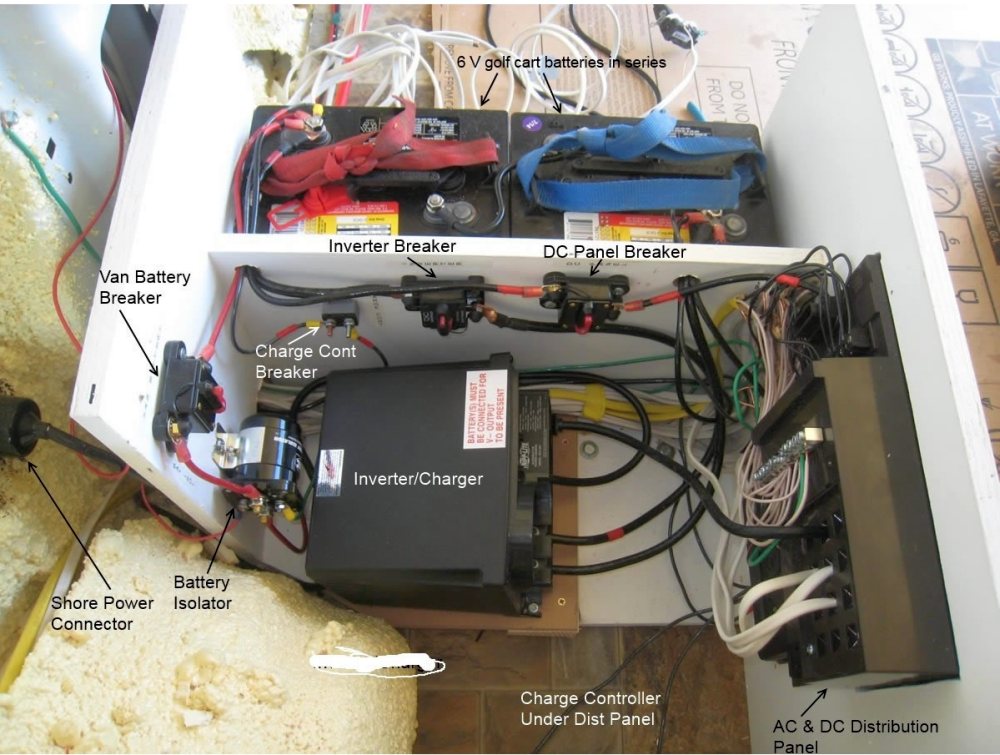 The breakers can also be used as switches to disconnect each function.
The breaker marked “charge controller breaker” has since been changed to one that includes a manual reset so that it can be used to manually turn off the solar charging if needed.
The distribution panel on the right serves as both the DC and AC distribution panel — AC on forward end and DC on aft end.
The breakers can also be used as switches to disconnect each function.
The breaker marked “charge controller breaker” has since been changed to one that includes a manual reset so that it can be used to manually turn off the solar charging if needed.
The distribution panel on the right serves as both the DC and AC distribution panel — AC on forward end and DC on aft end.
Venting
The battery compartment is vented to the outside to prevent any buildup of Hydrogen in the compartment.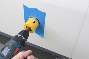
Shore Power Cord
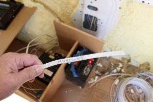
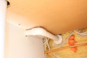
Its handy to have the things like the cord to hook up to shore power, the hose to fill with fresh water, and the hose to drain the grey water where they are easily accessible from the outside (where you use them). An outside compartment (say under the van) would be ideal for this, but I could not find a good spot. I decided to stow them on the back face of the bed platforms where they can be easily accessed from the outside via the back doors.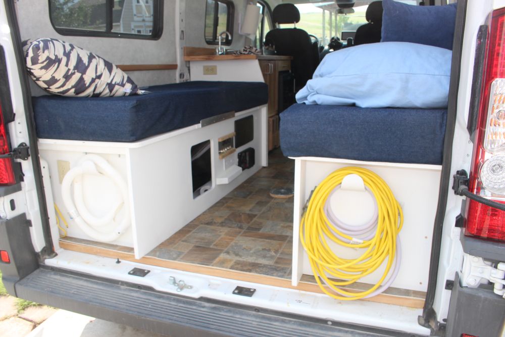 The shore power cord (50 ft extension cord) and the fresh water fill hose are hung on the back of the passenger side bunk, and the grey water drain hose hangs on the back of the driver side bunk. This has worked out nicely.
The hangers are homemade out of short sections for 3 inch PVC pipe and screwed to the bed platform back wall.
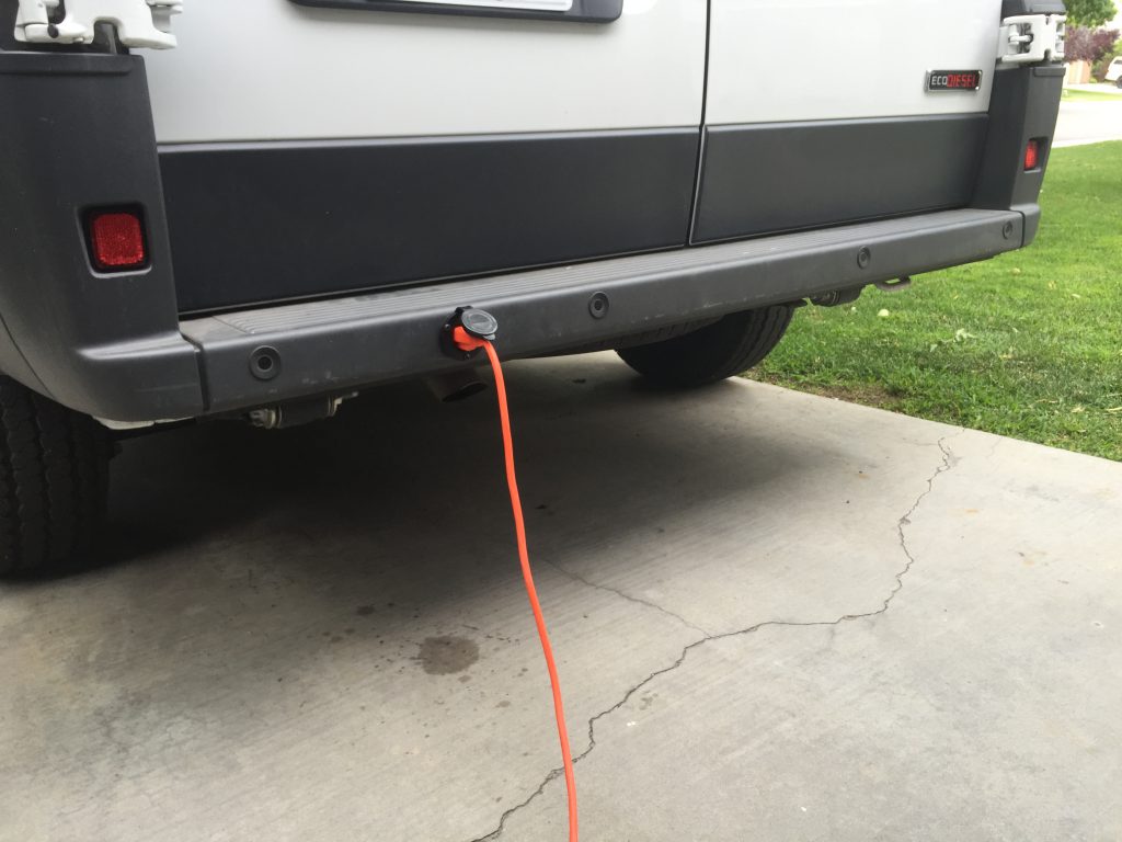
Note Comments section at the end of this page — Tyler shows a way to put the shore power receptacle in the ProMaster bumper — so, no hole in the side of the van. He also shows a very simple way to do a single AC circuit for the van with one very simple and cheap fuse and switch arrangement that you can buy at Home Depot.
The shore power cord (50 ft extension cord) and the fresh water fill hose are hung on the back of the passenger side bunk, and the grey water drain hose hangs on the back of the driver side bunk. This has worked out nicely.
The hangers are homemade out of short sections for 3 inch PVC pipe and screwed to the bed platform back wall.
Note Comments section at the end of this page — Tyler shows a way to put the shore power receptacle in the ProMaster bumper — so, no hole in the side of the van. He also shows a very simple way to do a single AC circuit for the van with one very simple and cheap fuse and switch arrangement that you can buy at Home Depot.
Distribution Panel
This pictures shows the AC and DC distribution panel (top) and the solar charge controller (below). They are mounted on driver side bed enclosure facing the aisle between the two beds.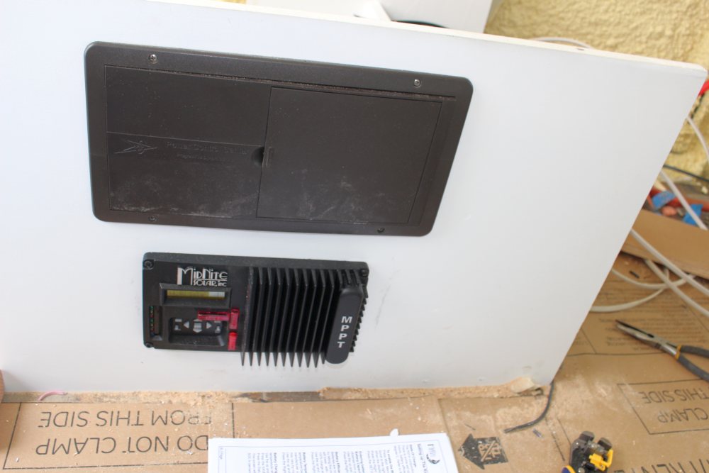
Switch Panel
I just recently added a small panel that adds on/off switches to the furnace and to the pump, and provides some extras for future use. It also provides 12 volt DC and USB charging outlets as well as a small volt meter to provide for easily monitoring the house battery voltage.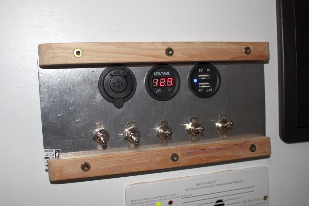 The switch panel mounts next to the fuse panel on the vertical face of the driver side bed platform.
The two switches on the left are pump and furnace, and the remaining switches are spares for future use. We have always found it to be a good idea to turn the pump off when not in the RV, as any kind of leak or faucet left on will cause the pump to run and drain the tank and them damage the pump. The switch on the furnace allows you to completely turn the furnace off and still have other DC gadgets powered up.
The top row has a 12VDC outlet, then volt meter, then a dual USB outlet.
The blocks of wood on the top and bottom are to keep things from hitting the switches and accidentally tripping them.
I have not updated the wiring diagram to show this panel, but the switches are in the plus lead between the fuse and the the furnace or pump, and the switches should be rated to at least the same current as the fuses.
The switch panel mounts next to the fuse panel on the vertical face of the driver side bed platform.
The two switches on the left are pump and furnace, and the remaining switches are spares for future use. We have always found it to be a good idea to turn the pump off when not in the RV, as any kind of leak or faucet left on will cause the pump to run and drain the tank and them damage the pump. The switch on the furnace allows you to completely turn the furnace off and still have other DC gadgets powered up.
The top row has a 12VDC outlet, then volt meter, then a dual USB outlet.
The blocks of wood on the top and bottom are to keep things from hitting the switches and accidentally tripping them.
I have not updated the wiring diagram to show this panel, but the switches are in the plus lead between the fuse and the the furnace or pump, and the switches should be rated to at least the same current as the fuses.
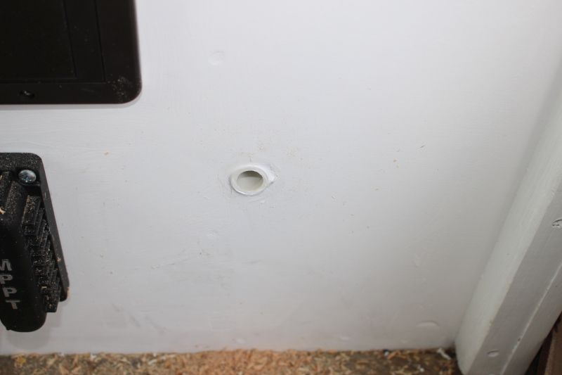
Solar Charge Controller
The charge controller goes between the PV panel and the house battery and regulates and optimizes the charging of the battery. It also prevents the PV panel from overcharging the battery. The MidNite Solar KID charge controller is mounted in the bed enclosure just below the distribution panel. This means you have to get down on hands and knees to read the status, but it does keep the wire runs short and the electrical bay compact. If we decide to do upper cabinets (above the windows) in the van, I may move the charge controller to one of the upper cabinets for easier reading — I’d convert the hole for the current position into an air vent to ventilate the electronics area. There are several status screens that display various info about the solar charging — e.g. PV panel voltage, battery voltage, PV panel watts, …
Solar Panel Install
Full details on the solar panel mounting and wiring here…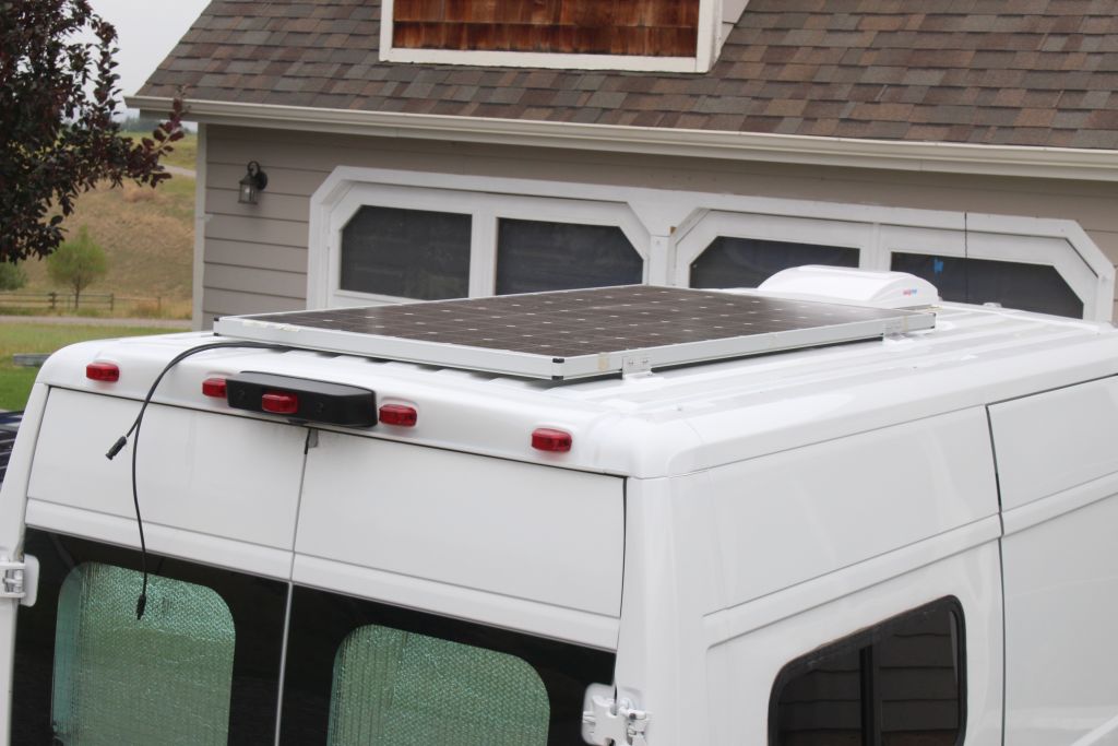
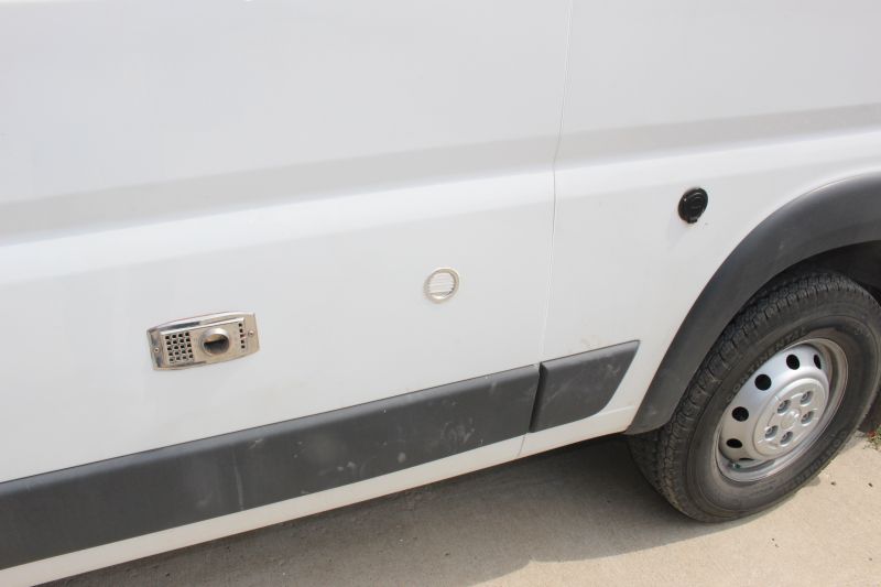
Shore Power
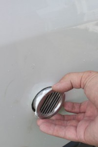
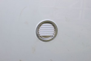
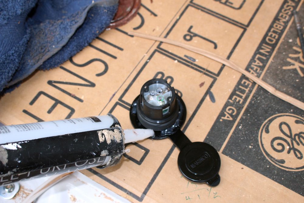
Since our AC loads for the camper are small, I decided to just use a 15/20 amp shore power connection — this is just a regular 12 gage extension cord that plugs into an ordinary 120 VAC outlet. Most RV’s now use 30 amp or 50 amp shore power connections, but with our small AC loads we just don’t need that. This is the through wall connection we used: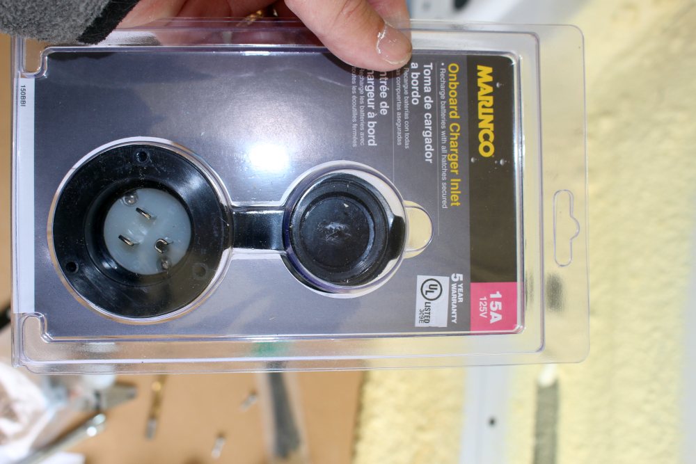 A bargain by RV part price standards at only $15.
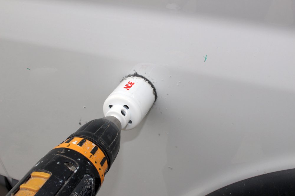
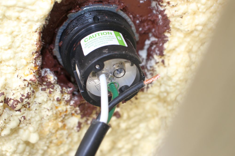
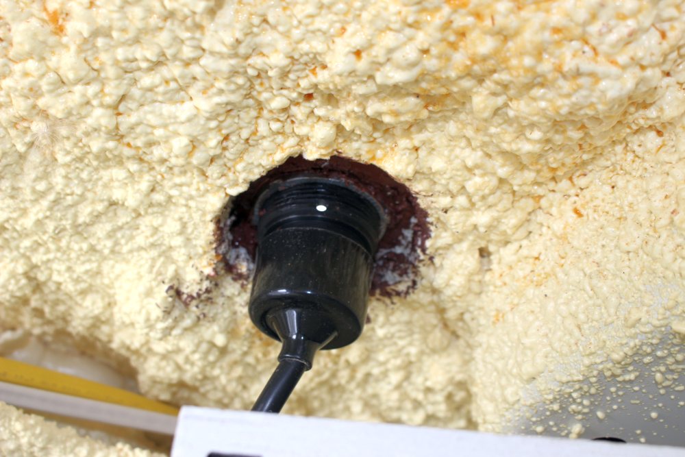
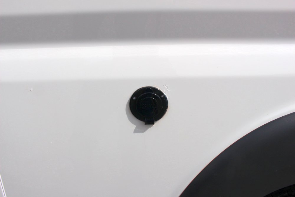
These pictures below show installing the shore power receptacle.
A bargain by RV part price standards at only $15.
These pictures below show installing the shore power receptacle.
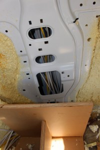
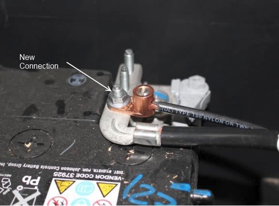
Connection to Van Battery
The connections to the van battery are shown below. I just used some unused connection points on the ProMaster battery terminal lug.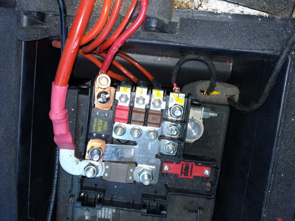
Adding A Battery Monitoring System
A Battery Monitoring System basically tells you with good accuracy how much juice is left in your battery at any time. It works by first sensing when the battery is at full charge, and then monitoring all the current going into and out of your battery and summing this up to let you know how much capacity is left. This is not a must item at all, but it does provide some useful information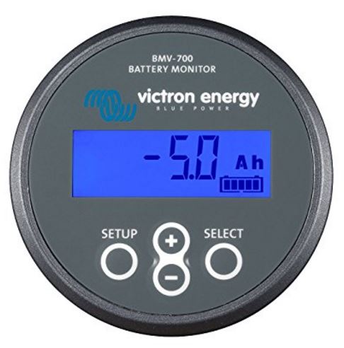
Securing Heavy Components
The batteries weigh about 60 lbs each and the Inverter/Charger is also heavy. I was concerned about these breaking away in a crash and coming forward to injure passenger or driver. So, this end of the bed box is bolted down through the floor with five 3/8 inch steel bolts. The other end of this bed houses the propane bottle and is bolted through the floor with several more bolts. The bed boxes are made out of a premium quality MDO plywood with all joints glued and screwed.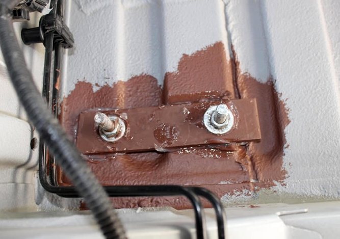
Electrical Loads Estimate
I did a rough estimate of the power use while in camping mode, and estimated the battery size and PV panel size needed to support this load for a couple days. I have assumed an 80% battery discharge level in these estimates. I know that batteries will last longer if only discharged to 50%, or even less, but if you look at the Trojan estimate for number of charge/discharge cycles for an 80% discharge, its about 750 cycles. For an RV that only gets used maybe 30 days a year, 750 cycles is about 25 years, and I’m sure the battery will die of something else before 25 years. Maybe I’m missing something? The spreadsheet also includes a rough heat loss calculation to get the furnace size and the power drain for the furnace fan and electronics. This came out to about 3000 BTU/hr with 32F outside and 68F inside the van — this is for an insulated small van. If you have something that will view Excel Spreadsheets, download Excel Spreadsheet here… Otherwise, table below is copied out of the spreadsheet, but its hard to read because of the formatting.| Van Conversion — Electrical loads Estimate | |||||||||||||||
| These are loads for one 24 hr period. | |||||||||||||||
| Available Power From Battery | |||||||||||||||
| Battery size (amp-hr at 12V) | discharge depth | voltage | Energy avail (wh) | ||||||||||||
| 100 | 0.8 | 12 | 960 | Trojan SCS150 RV/Marine battery: 100 ah, 11.3 L X 6.7 W X 9.8 D | |||||||||||
| 200 | 0.8 |
12 |
1920 | This could be two of the Trojan 6V golf cart bats (or two Costco golf cart bats) in series | |||||||||||
| Might want to just leave space provisions for the 2nd battery. | |||||||||||||||
| Assumed below that things that are on all the time (CO detector, fridge) will run off the battery for 16 hours — that engine running or solar will take care of the rest) | |||||||||||||||
| Solar Panel: | |||||||||||||||
| Based on the stuff below, you would want the solar panels to put in about 500 wh over the day. | |||||||||||||||
| Electrical Loads: | |||||||||||||||
| Item | Usage | Time (min) | Wattage | Energy (wh) | |||||||||||
| Lights | three LED at 3.5 watts each? | 180 | 10 | 30.0 | |||||||||||
| water pump | 6 | 40 | 4.0 | ||||||||||||
| TV | 60 | 20 | 20.0 | ||||||||||||
| Hair Dryer | 4 | 500 | 33.3 | ||||||||||||
| Furnace fan | 210 | 22 | 77.0 | This is based on 14 hours per day when heating is needed at 25% load factor (see below) with 12K furnace, or 210 min | |||||||||||
| computer | 90 | 40 | 60.0 | ||||||||||||
| Fantastic fan | 30 | 21 | 10.5 | low 1.3 amp, hi 1.75 amp (note that this would be much higher for summer, but furnace would be lower) | |||||||||||
| CO detector | 960 | 1 | 16.0 | the 1 watt is just a guess — should find out | |||||||||||
| LP gas detector | 960 | 1 | 16.0 | the 1 watt is just a guess — should find out | |||||||||||
| Fridge | THIS ONE NEEDS REFINEMENT | 960 | 12 | 192.0 | This is roughly based on Jeff Yago’s article times about 3X — still seems kind of low. | ||||||||||
| 0.0 | |||||||||||||||
| Total | 458.8 | watt-hrs per day | |||||||||||||
| Optional added loads | |||||||||||||||
| microwave | minimal use if not on shore power | 0.12 | 700 | 84.0 | |||||||||||
| Notes: | |||||||||||||||
| Fridge: | |||||||||||||||
| * with this setup, and 80% discharge, the 12 V – 100 AH would be good for about 2 days, and the 2 6V 225 AH would be good for about 4 days (both probably less in the real world) | |||||||||||||||
| * JY says that good fridges use 2 to 3 ah/day per cf — conservatively use 4 ah/day-cf. | |||||||||||||||
| A 1.7 cf fridge then uses (4ah/day-cf)(1.7 cf) = 6.8 ah/day, or (6.8 ah/day)(12 volts) = 82 wh/day, with an average draw of 3.5 watts (seems low) | |||||||||||||||
| Dometic says 40 watts, but this would be 365 KWH per year, which seems high for a tiny RV fridge. | |||||||||||||||
| Need a better source for power used by the Danfoss compressor fridges. | |||||||||||||||
| * At 0 F outside temperature, the furnace would be on twice as much and furnace watt hours would be 150 ish. | |||||||||||||||
| http://www.rvfurnace.info/ | |||||||||||||||
| * In summer, more fan operation might add as much as 200 or so wh, but furnace would drop to 0 (-62 wh) | |||||||||||||||
| * adding a microwave even if operated on battery would not be too awful as long as time of use is limited. | |||||||||||||||
| Van heat loss : | |||||||||||||||
| Item | area | R value | Tavg outside | Tin | Heat loss (BTU/hr) | ||||||||||
| walls | 210 | 6 | 32 | 68 | 1260 | ||||||||||
| Floor | 78 | 9 | 32 | 68 | 312 | ||||||||||
| ceiling | 72 | 6 | 32 | 68 | 432 | ||||||||||
| windows single | 30 | 1.5 | 32 | 68 | 720 | ||||||||||
| windows double | 18 | 3 | 32 | 68 | 216 | ||||||||||
| infiltration | 468 | 32 | 68 | 82 | at 3.0 ach | ||||||||||
| Total Heat Loss | 3022 | BTU/hr | |||||||||||||
| So, a 12K BTU/hr furnace would be running (3022/12000= 25% of the time) | |||||||||||||||
| Propane burn per day would be (3000 BTU/hr)(24 hrs)/(92000 BTU/gal) (0.8 efic) = 0.97 gal/day | |||||||||||||||
Solar Panel Charging:
Using PVWatts as a rough way to estimate output…For a 315 watt panel mounted horizontally in Billings MT, the average output per day is:This is with average weather for Billings — you can, of course, have full overcast days with very little production. Our estimated use per day is about 400 watt-hrs, so for most of the year, on average, a 315 watt panel would easily meet our daily needs even with the horizontal tilt. For the deep winter, the panel only meets about 75% of our daily usage, but if it could be tilted, it would meet our daily needs with a bit of margin. The above are with a PVWatts service factor of 0.77 — the real world one may be a bit less than this with the battery charge/discharge inefficiency included. Note that PVWatts has a bug that results in inaccurate output with arrays smaller than 1 KWH, so you have to put in a larger array, and then just scale the output numbers down.1575 watt-hrs per day in July 440 watt-hrs per day in October 300 watt-hrs per day in December With tilt equal to latitude (46 deg), the July number goes to 1450 wh/day and the Dec output goes to 800 wh/day.
How Has It All Worked Out?
After three trips in the camper van, I’d say the electrical system is doing fine. It runs all of our loads fine, including the two main loads: the fridge (about 42 amp-hrs per day) and the furnace (about 20 amp-hrs per day). There have been no malfunctions, and the only maintenance was to add water to the battery once. The solar panel has only been in place for the last trip, and its performance has been fine. While I have not carefully analyzed this, I think that for Spring, Summer, and Fall trips the solar panel will be able to provide all of the juice needed on sunny or part sunny days. Dead of winter trips are harder because the sun is lower and there are more cloudy days. I’ll try to log some actual data on how the solar charger performs with no charging from the van alternator on the next trip. At some point, I may add a TriMetric system to keep better track of the battery pack state of charge, but this is probably more out of satisfying curiosity than actual need. 2019 Update: The van now has 5 years and 70K+ miles on it and the electrical system has held up well. No significant problems or changes 🙂Weights, Costs, Labor
I did not keep track of the time spent installing the electrical system as it was spread out over a month. It was probably roughly the equivalent of 3 full days. Gary September 18, 2014
Item Description Weight (lb) Cost ($) House Battery 2 @ 6 volt, 200 AH golf cart batteries (Costco) 120 $180 Inverter/Charger Triplite APS 1250 Inverter/Charger 23.2 $406 Battery Isolator PAC-200 Battery Isolator 200 amp 2? $46 MPPT Charge Controller Midnite Solar KID Charge Controller 6 $280 AC/DC Distribution Panel PD5000 AC/DC Power Control Panel 2? $58 PV Panel SolarWorld SW315 PV panel 49.6 $368 Circuit breakers 2? 64 Wire #14 and #12 Romex 220 ft #14 Romex, 25 ft #12 Romex 14.6 $40 Other wire #2, #8, #6 short lengths 15? $30? Terminals 1? $20? Shore Power receptacle 1 $15 Inside lights, … TBD TBD Total 236 $1507
I am impressed of your article. I want to buy solar panels too
Wow!! Amazing blog. Solar panel installation is important for saving money and the environment. Solar panels are an excellent way to save money on electricity bills because they generate the electricity you use for your home.
Hi David,
I’m a strong supporter of solar for both homes and vans, but for vans there vans there is a caveat on the environmental front.
Solar panels on a van definitely charge the house battery and reduce the carbon emissions that would go with charging the batteries from the van alternator. But, the roof mounted panels also cause aero drag and this makes the van consume more gas when driving. So, ideally, the PV panels are installed in such a way that the aero drag increase for the van is small to none. This could be the flexible PV panels mounted right to the roof surface, or a conventional panel mounted in as low drag a configuration as possible.
In general, mounting the PV panels low to the roof and as far back as possible decreases drag. Some testing I’ve done also indicates that an elliptical nose fairing on the front edge of the panel reduces drag.
Search around on this site for “drag” to see some test results.
Gary
Gary
Do you remember what size/ particular bolts you used were to connect the fuse on the positive side of the van battery in the slot thats available? I noticed its just empty slot when going to install.
Hi Andrew,
I don’t remember right off hand – I’ll see if I can take a look today.
Gary
Thanks! No rush. Appreciate the help.
Hi Andrew,
All of the bolts in the lower left corner of the picture of the wires coming into the van battery are 8 mm. I don’t think the length is critical – maybe about 3/4 inch?
Gary
Thanks so much! Appreciate you taking the time to check.
Love your site and clear, descriptive explanations! Read all your comments in the forum – always the common sense answer.
Don’t understand the daily use you talk about above. If your fridge uses 42 AH, does this not equal 500 WH on its own? You talk about daily use of about 400 WH, easily covered by the 315W solar panel. I’m new to the electrics, and trying to figure out my needs. About the same uses as you, fridge, fan, shurflo pump, led lights, usb chargers, small monitors, maybe a small AC coffee maker. (650 watts). 330 watts of solar and 2 110amp batteries.
Hi,
Good pickup – thanks.
I wrote the stuff above before doing the actual test on fridge energy use. I used an estimate on fridge watt-hrs from another source and it turned out to be optimistic.
I’ll rewrite the above section based on actual experience over the last 5 years.
Just looking over the table of loads after 5 years of usage, I think the fridge is the only one that is way off, but in hindsight some of the other durations for some of the loads seem a bit higher than actual.
Gary
I love your design and will be copying it pretty much the same for my van. I have a few differences if I can ask? First, I want to use an 120v rc fridge plus add 5k-7.5k btu window unit in rear door (not window). Will use hand pump with (spring)water jug no pump, no hair dryer no furnace. My question is, and I think I know the answer, do you see a problem with 120v fridge and A/C unit on same system as yours and have fridge run while driving? Thanks
Hi Edward,
The 120VAC fridges work in RV’s and a few people use them. But, most find that in the end its worth paying up for the 12 volt RV models even though the price premium hurts. The 12 volt models are more efficient and they don’t require running the inverter all the time (which eats some power).
The 120VAC fridges may require a pure sine wave inverter — not sure.
The 6K BTU AC would be by far your largest load. Probably about 500 watts or about 46 amps out of your 12 volt battery all the time its running. You would not be able to run it very long off the two golf cart battery setup — a couple hours would discharge down to 50%.
You mention driving while running the AC — this would help, but I think its unlikely that you would get enough charging from the van alternator to keep up with continuous AC use. About the best I’ve seen on sustained charging is 30 amps.
Most of the people who try to use an AC in a van on batteries have huge battery packs (eg 600 amp-hrs) and still can’t run the AC all the time. Its a tough problem. Most people end up resorting to shore power or a generator.
For the kinds of loads you are talking about, you would definitely want to go with a better inverter/charger than I did, and one that is pure sine wave — especially since the price premium for these has dropped.
Gary
I would just run fridge while driving to camp then connect to shore power,,,no a/c whiling driving just fridge. Thx
I’m going to just use unit (inverter) for fridge when driving to shore power, maybe phone charger etc no air conditioning while driving. I will use shore power for all other appliances. Question? I have 30 amp shore power chord and wish to connect to 30 amp service while at camp sites but use 15 amp adapter while home to charge batteries etc,,,,,I assume just use 30 amp out instead of 20 amp which you used???? will it wire the same just different plug for 30 vs 20 amp? Correct? thx
Hi,
Yes — I think that should be fine.
Gary
Gary,
After doing my van build (following your advice), I cannot help but notice when see products that might be better for the next time. I’m interested in this battery isolator. It’s the voltage sensing kind. https://www.amazon.com/dp/B0058SGDFK/
What do you think?
Hey Dennis,
I think its fine — not sure its better.
There has been a lot of discussion of the doctor on the PM forum — some people think its the cat’s meow, others not so much.
You get the button that allows you to parallel the batteries for a jump start when van battery is down, but you can do the same thing with a little jumper wire and a regular isolator.
I think it just comes down to whether you think the extra functions are worth the extra complications and cost. I think I would probably just go with a regular isolator if I was doing it again — kind of a personal taste thing I think.
Gary
I’m doing a cargo trailer conversion and am curious how you wired the Inverter/Charger to your shore power as well as to the AC breaker. This wasn’t clear to me and I didn’t want to make any assumptions. Thanks.
Hi Roman,
My inverter charger on its 120 VAC output had a cord terminated with a regular female 120 VAC plug. I cut the plug off and wired 1) the hot wire to the main breaker in the AC distribution panel, 2) the ground (green) wire to the ground bus in AC panel, and 3) the neutral (white) wire to the AC panel neutral bus. The inverter/charger automatically connects this 120VAC out wire to either shore power (if plugged in) or to the inverter (if enabled). It also takes care of bonding the neutral wire to the ground at the inverter charger and unbonding it if you are on shore power.
The shore power connection basically just a cord with a male plug that comes out of the inverter/charger and plugs into a 120 VAC shore plug at the campground power pedestal.
The line on mine is broken by the outside socket installed in the van skin so I don’t have to run an extension cord through a door or window.
There is also a ground wire from the inverter/charger that I connected to the ground bus in the AC panel.
I don’t actually recommend the model of inverter charger that I got as there are better cheaper ones out there now — including ones that have pure sinewave inverters.
You always want to follow the hookup instructions in the manual.
Gary
Which newer inverter/chargers do you like instead of the Aps1250? The 1250 looks pretty good and tough with auto mode etc,,,which others do you perfer?
Hi Ed,
The APS 1250 has been reliable and I think TripLite makes good stuff. But, its not a true sinewave inverter, and some things won’t run on it.
I have been looking at inverter/chargers lately, and one that I like is this one:
https://www.donrowe.com/samlex-evo-1212f-pure-sine-inverter-charger-p/evo-1212f.htm
Gary
Great, I have a APS 1250 and next time I will look into true sinewave.
I want to use (1)maybe (2) AMG 12v 100ah batteries because no spill, less venting, plus I can’t find a 6v under $200 in this town. I understand the 6v is a better system but don’t like “flooded” inside my van. Your thoughts?
Hi Ed,
It sounds like you understand the tradeoffs between AGM and flooded batteries. Most people do choose AGM’s. Its just a case of looking at the pros and cons and picking the one you like the best.
If you do plan to use the inverter to run largish AC loads, I would go for the two 100 amp-hr batteries rather than just one — the inverter draws a lot of current with larger AC loads and would likely be beyond the peak current a 100 amp-hr battery can provide.
The 200 amp-hrs also gives you more reserve. If you plan to use an electric fridge, this alone will use about 40 amp-hrs a day, and you should never take the battery below 20% state of charge.
Gary
Question: Cannot see any detail pics on your build for this: For the electrical outlets, whether 120VAC or 12VDC, are you using standard 2×4 boxes, or just running the wires bare to the back of outlet plates, with them secured thru the paneling? Or are they mounted in the steel cutouts in the PM walls? (Have to sort these things out BEFORE insulating and paneling, right??)
Hi Dave,
All of my 120 VAC outlets are in standard residential plastic outlet boxes — wired just the way they would be in a house.
I think that all of my 120 VAC outlets are in the galley cabinet and in the bed pedestals, so I did not have to figure out how to mount 120 VAC outlets to the van wall or paneling.
We have actually found that we don’t use the 120 VAC outlets very much — most of our stuff is 12 volt DC. But, still need a couple 120 VAC outlets.
Gary
I have the same inverter/charger and distribution panel as you, and I too cut off the plug end of the input cable (7B) and wired it to my shore power elec. entrance. I was planning on using the left over plug end to plug into the inverter/charger’s output receptacle, and to then route that cable end to my distribution panel’s AC bus bars.
However the wires in that cord are only 14 AWG, and would be overloaded before the 30 amp main disconnect breaker in the AC panel would trip. Is this not a concern?
Hi Jim,
Sorry about the slow response – we have been without internet up north.
I did the same thing and used the cut cord for both connections.
For shore power from van to power pedestal, I use a regular #14 extension cord and I plug into the regular 120 VAC outlet on the power pedestal, so its protected by the 20 amp breaker in the power pedestal. The nice thing about using the #14 extn cord is that a 50 footer takes up little space vs what a 50 ft #10 extn would.
The TripLite box itself may also provide protection on its outlet side — certainly when its on inverter, but maybe also when on shore power.
I do think that it would be good to either switch out the main breaker from 30 amp that it comes with to a 20 amp, or get a short #12 extn cord an cut the female end off and use it the way you were going to use the cut off TripLite cord.
I think I will pick up a 20 amp breaker for mine next time I’m down at the hardware — I know I thought about doing that when I first installed, but it fell out of my head.
Short story about current capacity of a #14 wire: I was changing out the circuit breaker box on the last house we had, and was finishing the wiring with the box hot to get the power back on sooner for the family. I had a #14 green insulated ground wire tied up to the ceiling above the box waiting to be hooked up. The wire got detached an swung down an its tip hit the main bus bar of the breaker box – big flash and then darkness. In about the zero time, the #14 wire blew the 200 amp main breaker. The plastic insulation on the ground wire was not even damaged. Obviously not a way to size wire, but interesting how much capacity a smallish wire has for hard shorts.
Gary
Here is a photo of how I routed the wires from the van battery to the house battery.
Hi, Great build! Can you tell me which wire is the “hot” wire that you connected to for battery isolator power? I have a Promaster 2018 and there is a black and a yellow wire leading fro the DC power outlet at the rear of the vehicle. Thanks! Any photos will be helpful!
Hi Patrick,
Unfortunately, did not take any pictures, and that area is kind of hard to get to now.
You can identify the + wire with a multimeter easily. If you don’t have one yet, the $5 ones from (for example) Harbor Freight work fine and are useful for lots of things.
Gary
Gary, You set the switch on the Inverter to Auto/Remote, plug in the ethernet cable to the Inverter and the Remote, and then the Remote Control switch will allow you to select either Auto or Charge Only. It doesn’t have the option to turn it off, but that makes sense.
Thanks Dennis
I thought I’d try again and see if it was upright.
Hi Dennis,
Vey nice.
Are the switches that are on the front of the inverter available from the remote? That is, can you switch between charge only and auto from the remote.
Gary
My location for the Tripp Lite inverter made it not easy to see, so I purchased a remote for the inverter on eBay.
I just finished the outside vent for the battery compartment. I used a common rv battery vent: https://www.ebay.com/itm/162915707716
The second vent hole you added is open to the inside of the van. Wouldn’t it be better to drill a hole in the bottom for fresh air intake?
Hi Dennis,
Nice looking vent.
I was reluctant to drill any more holes through the outer wall, so went with the inside inlet. The flow volume is very low, and it seems like there should be plenty of air inside the van to supply it.
Not even sure that there is any flow into the inlet vent in that the H generated in the battery cells is new gas, so it can rise out of the outlet vent without the need to pull in new air?
As mentioned above, I’m a bit skeptical of the whole venting thing, but decided to go with doing it by the rules.
Gary
Gary,
Are these the type of circuit breakers you used? If so, how many amps do you recommend?
https://www.amazon.com/60Amp-Circuit-Breaker-Marine-Stereo/dp/B076GVZYHX
Hi Dennis,
Its the same design and look, but I think the brand is different. The ones I used (I think) are just a generic China import.
I had one go out just a few days ago, and replaced it with a similar looking one that is made by LittleFuse — it might be worth looking for these as LittleFuse is a well know brand.
Sizes depend on what you are fusing.
Gary
Here’s a picture of the tabs that need to be bent in order to make proper contact with the breakers in the AC section of the distribution box. The tabs need to be bent to the left. That seems impossible, because they’re flat in that direction, but it works as apparently the hidden rod/connector in that they are all part of does bend. I was afraid the thin plastic box would break, but it didn’t.
It’s critical that the breakers make good contact with the tabs, otherwise arcing can occur. In my case, they were very loose, and contact was interrupted.
AH, Perfect! I haven’t tried it yet, but will this week. Thanks again!
Thanks Paul
Gary
I’ll take it apart tomorrow and take a picture.
Thanks a lot, Paul. Much appreciated :o)
I took Rick’s advice and bent the tabs. I was a bit reluctant, as I was afraid I might break the plastic housing that holds the rod and tabs, but it worked. And it made all the difference; now the breakers have good contact and are not so loose and wobbly.
Thanks Rick!
Can you possibly post a photo of just where to bend? I have the same problem – thought it was just how these things fit. Thanks to you and Rick for bringing this up and suggesting a solution.
Paul or Rick — if you have a photo, you should be able to post it using the “browse” button to select a file on your computer, which will be added to your comment reply.
Gary
Gary, What exact brand of breakers did you use in your box? I have the same PD5000 box and used Square D Homeline, one of the ones recommended, but they’re all really loose and wobbly, and now I’m having problems with them actually losing contact and turning off power.
I noticed how feebly the breakers fir in the first place, and frankly, I’m pretty disappointed with that aspect of the unit. This would not happen in a residential box.
Are yours in there securely?
I had the same problem using the same breaker and distribution panel. I found the problem with the panel, not the breaker. The post that the breaker clamps onto needed to be adjusted by bending it with a pair of pliers. I found the breaker was barely clamping onto the metal post. It was a simple fix. I hope that helps you.
Hi Paul,
The breakers I have are square D Type TIPO HOM
The 15s are DP4075 and the 30 is a PA5283.
I’ve not had any problems with them heating up or not making a connection, but now that you mention it, they do seem to fit kind of loosely.
Maybe try Rick’s suggestion — I think that I will.
Thanks Rick.
I’ll send an email into the manufacturer and see what they have to say.
Gary
Van conversion is slowly chugging along. As with all my projects, it takes longer and costs more than I thought. lol Where did you get the battery box vent cap that goes on the outside of the van. tried several different searches, so I thought i would ask you. Hope you remember!
Regards
Georg
Hi Georg,
It was a vent I bought at a local hardware store. Its alum and I think its intended use might be for home soffit venting.
Seems to work fine and not corroding.
I think I just installed it with silicone caulk.
Gary
Gary,
Thanks for your input on the investor/charger. I’m also looking for a solar panel equipment.
Here is a panel that is close to yours: https://a1solarstore.com/solarworld-plus-300w-solar-panel.html?gclid=EAIaIQobChMIscSh4pO-3AIViDaBCh106A6oEAkYASABEgIcyvD_BwE
Here is a controller:
https://www.amazon.com/Victron-SmartSolar-Charge-Controller-Bluetooth/dp/B075NPQHQK?th=1
What do you think about both of these?
Hi Dennis,
They look like good choices to me.
SolarWorld has a good reputation and they specifically mention hail and sand resistance, which might be more of an issue for a PV panel moving along the highway at 70 mph 🙂
The price per watt is good, but you also always want to consider shipping cost for PV panels. I ended up getting mine from our local Platt Electrical — the price per watt was a little higher, but no shipping charge.
I like the charge controller and its nice to see controllers coming out that handle the larger pv panels and don’t cost $400 (like the current price on our Kid controller). I have a Victron battery monitor and think it is well engineered.
One thing I’m not quite clear on is the 20 amp spec and whether it applies to the maximum charge current going into the battery. If the charge current going into the battery is limited to 20 amps, then you will be right at the limit with your 300 watt panel (eg 300 watts/13 volts = 23 amps). This is not going to happen very often, but on a full sun cool day you could get there. Question is, what happens when the charge current goes over 20 amps? Does it shut down, or does it just clip the charge current at 20 amps? Clipping the charge current at 20 amps (to me) would not be a problem as you are not going to get the full 300 watts out of the panel very often, but if it shuts down, that could be an inconvenience. I guess one option would be to go for the 30 amp model.
The other thing to think about is the Bluetooth interface. The up side appears to be that you get much more data on whats going on, the (maybe) downside is that its nice to have an actual panel on the controller you can take a quick look at any time without having to have your phone and having to deal with any sort of pairing or communications issues. I’d probably opt for the Bluetooth if I had the option.
If you get the charge controller, please let us know how it works out.
Gary
Gary,
I decided to go with the same refrigerator you used. Thanks for your great research! Now I’m working on electrical. This unit is larger than your Tripplite Invertor/Charger, but do you think it would be a good replacement? It’s about the same price.
https://www.hodgesmarine.com/Xantrex-Freedom-Hf-1800-Inverter-Charger-p/xan806-1840.htm
Hi Dennis,
Xantrex is a good brand and this looks like a good unit. Even thou its produces more power than the TrippLite, it looks a bit more compact, which is good. I like the display panel better than my TrippLite in that it shows more and is better oriented. Looks like a good unit to me.
About the only doubt I would have is whether you want to go for a pure sine wave one or not. As I mention on the electrical page, they have come down in price, so you don’t save as much as you used to by going for a modified sine wave. That said, there has only been one AC load that I’ve tried that did not want to work right on my modified sine inverter and it was not really something I needed.
The fact that they are pushing it for EMS service probably indicates they have a lot of confidence in the output wave shape.
If you get it, please let us know how it works out.
Gary
My electrical system is very much patterned after yours (thanks!) except that I have a 2000W Xantrex inverter. I tried running a microwave that was left behind by a tenant because it has a manual timer, so no parasitic drain. It draws 1000W. After about 2-3 minutes, the Xantrex shuts off. I watched voltage very carefully: it started at about 12.6 or so, and then drops fairly steadily until the Xantrex shuts off right at about 11.5-11.4 volts. The default low voltage cuttoff is supposed to be 10.5 V and I checked that it is on that setting.
I called Xantrex and they basically said there’s something wrong because the voltage dropped so quickly (from 12.6 to 11.5 in about 3 minutes) and that’s why it’s shutting off well before the 10.5 V low voltage cutoff.
I’m very inexperienced with 12V battery systems. I have new batteries just like yours, and my Victron shows them to be 100% when starting, and at about 96-97% or so after the 3 minutes or so. My battery cables are oversize and very short.
Do you have any suggestions/thoughts? Does that voltage drop seem excessive to you? I’d like to know that I can run this MW for at least 5-8 minutes or so.
Hi Paul,
Seems like your setup should work.
Maybe check that all the contacts are corrosion free and well tightened, but I suspect you have already done that.
If you have a Kill-A-Watt, you could plug the microwave into a regular house outlet and see what it actually draws. Microwaves are rated on output, so if its a 1000 watt output microwave, its probably drawing more like 1250 watts, which should still be OK.
They do make small 700 watt microwaves which actually draw like 900 watts — if you have access to one, you might try that.
If the batteries you got have tech support line, you might call them an ask if the batteries can supply about (1250 watts) / (12 volts) (0.9 ) = 117 amps.
amps plus more on startup. Where 0.9 is the inverter efficiency.
If they don’t have a support line, maybe see if max current is listed on the Trojan site for their T105 golf cart battery — Trojans are good, so brand X may not do quite as well.
I don’t understand the Xantrex statement that the inverter has a cutoff voltage of 10.5 volts, but sometimes it shuts off at 11.5 volts?
If the Xantrex is not a pure sine wave, I guess there is the possibility that the microwave does not like the power quality from the inverter, but seems like it would make noises and not work well rather than causing the inverter to shut down?
You might try seeing if running the engine while using the microwave. If that fixes the problem — I guess that would lead to the conclusion that batteries are not sufficient (or may microwave is drawing more power than it should).
It seems like people do successfully run a small microwave with two golf cart batteries, so I think something must be wrong.
Please let us know what you work out for a solution.
Gary
All my contacts are shiny new and very tight. It’s a 600W output microwave that draws just under 1000watts (confirmed with my KillaWatt). The Xantrex is pure sine wave; that’s why I got it.
I plugged in a 600w space heater; it ran about twice as long 5-6 minutes, but when the voltage dropped to about 11.5, the Xantrex shut off.
I need to find out how quickly voltage should drop, and whether 11.4-11.5 is low or not. But something is clearly not right; I assumed that running the microwave for 3-6 minutes was not going to be an issue.
Thanks.
Hi,
Battery capacity wise, the 1000 watt microwave should draw about 1000 / 12*0.9 = 92 amps. So, 6 minuites (1/10th hour) is only about 92 amps * 0.1 hr = 9 amp-hrs — so, not much of anything to a 200 amp-hr pair of golf cart batteries. I’d think you should be able to run this load for an hour without a problem.
I’ll try running a space heater off my battery and inverter tomorrow and note how fast the voltage drops, but that seems like a lot of drop for just a few minutes. Will let you know.
Gary
Hi,
I ran an 800 watt space heater off my inverter for 12 minutes with following .
Time in minutes from space heater turn on.
Voltage and current read on Victron battery monitor.
Space heater watts read on a Kill-A-Watt meter.
So, each line below gives time in minutes since space heater turned on, then battery voltage, then space heater watts, then (for some times) the current being drawn from house battery.
Time Voltage watts current
0 12.98 0 0 (no load)
0+ 12.17 800 82.7 (heater on)
1 12.10 763 81.8
2 12.06 760
3 12.04 770
4 11.97 780
5 11.93 758
6 11.87 762
7 11.82 780
8 11.79 778
9 11.78 774
10 11.77 804
11 11.75 780
12 11.74 778
13 turn on engine
13 12.52
Initially, the battery voltage drops fairly quickly when space heater load is applied, but toward the end of test, the voltage drop rate per minute slows down — I think it would have continued running for quite a while without a problem.
I guess a tentative conclusion is that your two golf cart batteries should be able to run your microwave OK. Seems like most likely problem is bad batteries, or bad inverter. Checking with your PM engine running might help to shed some light?
Interesting thing is that about a minute after I turned the engine on, the breaker in the charging line from the van battery (alternator) to the house battery popped. Its a 60 amp breaker, and has never popped before. So, I guess the alternator was trying to supply some of the current for the space heater and went beyond the 60 amp breaker capability. So, if you plan to run the engine during times when microwave is on, plan the line and breaker from the alternator/van battery accordingly.
Please let us know what the problem turns out to be.
Gary
Thanks for that. It’s about what I would have expected. Something is clearly off.
I bought the interstates like yours from Costco early this spring. I wanted to dry run the electric system so I set up the solar panel and Kidd solar charger in the back yard, and I called Interstate to get the charging specs on those batteries, and set up the Kidd with them. And they sat there for months at full charge. I also hooked up the inverter too and made a few short test runs, but not more than very brief ones.
I need to figure out whether it’s the batteries or the inverter. Dang; I sure hate to take it all apart now that’s it’s all hooked up and bolted down in the van.
I haven’t even tried to run the engine yet with a load on it. The solar panel and charger must be contributing a bit too while the load is on.
The charge voltages I got from Interstate were: 13.8 absorb, 13.5 float, 13.5 equalize.
When there’s no load, my battery voltage is in the 13.6-13.7 range. Seems a bit high, but that’s what they gave me. But the moment a load is on, it drops to about 12.7 or so.
One more thought: voltage drop due to resistance. I used 2/0 welding type cable, which is safely above the Xantrex recommendations, and the runs are extremely short, as the setup is similar to yours. Big solid copper lugs. All very tight. But I did wonder about the 250A main breaker, a cheap Chinese unit. It seemed rather light weight to handle that much juice, including its smallish lugs. I wonder if it’s possibly a source of resistance?
I guess you could short around the breaker for a short time with a heavy wire to see if the breaker is the problem. Or, maybe just replace the CB if it seems suspect?
Gary
Gary. Just as I thought: that cheap breaker was the problem. Bypassed it, and with the 1000W MW on, voltage dropped quickly to 11.7-11.6, but then stayed there rock steady.
What kind of main DC breaker did you use?
Also, just to confirm what you told another commenter regarding that AC/DC panel: the AC side should not have a link to chassis ground, right? There were no instructions with that panel, so I wasn’t sure, but I had my doubts.
Hi Paul,
Nice that it turned out to be a cheap part rather than the batteries or inverter.
I just used a generic 12 volt breaker from Amazon, but if you want a higher quality breaker, I’d have a look at what BlueSea or maybe Bussman has — both good brands.
The way I understand it is that the on the AC side, the neutral and ground should be tied together at only one point. When on shore power, this point is back at the power pedestal the campground provides, but when you are on the inverter the tie point should be at the inverter. So, the ground/neutral tie point changes between shore and inverter power. Most of the inverter/chargers will handle this automatically when you go from one to the other. If you are using a standalone inverter, then this is something to look into — I think you will have to switch the ground neutral tie point with wiring and a switch you provide, but I’m not sure.
The reason for doing it this way is a safety issue. With certain kinds of failures, you can get a hot chassis situation if the ground to neutral tie point is not in the right place and only in one place.
Gary
Hi Gary,
I’ve finally gotten down to putting in the electrical system in my van conversion, and have some questions about the PD-5000 DP — I have the same one, but I’m really confused about a couple of things, so I apologize in advance for being so dense.
First, on the DC side: where does the cable from the house battery connect to the panel? I see the two bus bars on the rear, one directly behind the DC fuse panel (assuming these are the positive connections), and the one behind the AC breakers (this is the DC negative bus, correct?). The only other place I see that is a candidate is the small protrusion, also behind the DC fuse panel, that has two screws in it, but I can’t figure out what type of connector to use, if that is indeed the DC input. And why are there 2 screws there? I thought the DC negative bus should be connected to the battery negative terminal and/or chassis ground – is the second connector supposed to be connected to the battery negative?
OK, now for the AC side: I see a neutral bus and a ground bus; again, I’m assuming the ground bus gets connected to a chassis ground (although I notice you said you’d forgotten to do that until much later), but what does the neutral bus get connected to? Should that be connected to the inverter [AIMS 2000W inverter/converter] negative terminal?
Thanks again for your great website and all the great discussion on this site!
Lorraine
Hi Lorraine,
The system seems to have eaten my earlier answer, so will try again.
The place you see as a candidate is the right place to hook up to the house battery. Just use one of the screws and leave the other disconnected. Definitely do not hook the 2nd screw up to the neg terminal of the house battery — this would cause lots of fireworks.
You are also right on the two bus bars on the back of the DC panel — the one that is insulated between screws is for the positive wires going to your DC loads (each screw is connected to its own fuse). The non-insulated bus is for the negative return wires from your DC loads.
For the AC side…
On my setup, there is a standard AC three wire cord from the inverter output to the PD panel – black (hot), white (neutral), and green (ground) wires. The black is connected to the main breaker of the PD panel. The white goes to the neutral bus in the PD panel, and the greeen goes to the ground bus in the PD panel.
I have a chassis ground on the DC ground bus of the PD panel (this is the on I initially forgot to hook up). But, the neither the AC neutral and AC ground busses have a chassis ground. The inverter/charger automatically takes care of bonding the neutral and ground busses together when you are not on shore power, and not bonding them together when you are are shore power, as they will be bonded at the power pedistal, and should only be bonded at one place in the system.
Keep in mind that I am not an electrical engineer or electrician, so take my advice with a grain of salt!
Gary
Haha – I completely understand the caveat! I just wanted to be sure I knew what connection on the DP connected to what, since it’s not always very obvious, and since you had the same device, you were the perfect person to ask.
BTW, I asked you a while ago about the Projecta IDC-25, and I decided to go with it, so I can’t wait to get everything running to see how it turns out. It’s very compact, and very sturdily wired-up, with great instructions, so I’ll let you all know how it goes.
Please let us know how the IDC-25 works out.
Gary
Hi Gary, I’m close to finishing our electrical system and I have a question about the alternator charging of the house batteries. You have a 50 amp breaker at the house battery and it looks like you used a 100 amp mega fuse at the van battery. with the 50 amp breaker that mega fuse will never blow. what am I missing? I’m tempted not to install any fuse at the van battery since the circuit is already protected by the 50 amp breaker. please give me your feedback on this.
Hi Rick,
When you have current sources (batteries) on both ends of the wire as you do with the wire that goes from van battery to house battery, you need fuses on both ends. Each fuse should be as close to its battery as possible.
Reason for this is if you only have one fuse, and the wire shorts to ground anywhere along the wire, you will have a short circuit directly to ground from one of the two batteries. You need the fuse on each end (close to battery) to protect the wire.
I use that smaller breaker on the house battery end so that I will be alerted if the charging current goes above 50 amps. The battery manufacturer says battery life for my batteries will be shortened for high charging currents.
Hope that explains it?
Gary
Gary, I’ve read through this twice now but I still don’t understand clearly what you’re doing with the bare ground of the Romex on the 12v circuits. They’re totally useless, functionally, right? Or am I missing something? What do you do with the bare ground on the fixture end?
You say “Seems like I terminated the white and ground wires on the same negative bus on distribution panel. Then a wire connects the negative bus to the common ground connection point I described before.” But what about the fixture end? You join them there too, presumably. But does having two negative/grounds really add anything other than duplication? I assume it beats not using the ground at all, but I’m curious as to the rationale. Too bad thye don’t make two-strand shielded cable like the old days. 🙂
Hi Paul,
As near as I can remember, if the fixture end had a separate frame ground connection, I hooked the bare ground to it. If not, I just did not use it.
In AC wiring, the bare ground wire is to ground the frame or housing of the appliance you connect it to. It does not actually carry in current under normal circumstances — its there to ensure that if the appliance housing gets shorted to the hot wire the ground wire keeps you from getting electrocuted by the hot casing and blows the fuse. While this is not normally done in DC wiring, you could use the ground wire in the same way.
But, I do agree that the bare ground is not really required for the DC circuits, and I guess one approach that I don’t think would have any safety or functionality issues would be to just cut the ground wire off back to the point where you strip the sheathing on the Romex.
Gary
Hey Gary,
Just getting going on our electrical installation and had a few questions. We have the same distribution panel as you – does it need fuses installed for the DC circuits to work?
We also have the same inverter/charger as you and were wondering if it makes any noise while running?
Thanks,
Abby
Hi Abby,
Yes, you will need DC fuses for the panel. These are the cheap, two bladed automotive type fuses.
The inverter/charger makes a very low hum when running — I can’t hear it except when my ear is right next to it.
Gary
Hi George
I looked through all the settings and options I could find on my end to try and find something to unsubscribe you, but no luck.
The nice thing about doing sites with WordPress is that they take care of so many of the details, but can be frustrating when you want more control.
I will try “unapproving” all the posts I can find for you, and maybe the comments system will be smart enough to stop sending you stuff.
The only other things I can think
of:
Go to the WordPress.org forum: https://wordpress.org/support/ and ask the experts there what can be done. I think that whatever can be done is probably on your end, but if I can do something from this end, let me know.
On your email, filter out emails from my site — ie put me on the spam list.
Wish I had a better answer — Gary
Gary, Hate to bother you again, but the KID solar charger wants the specific charge voltages for our specific batteries (same as yours), for absorb, float and equalize. I couldn’t find them at the Interstate web site. Did you find some specs for them, or?
Thanks.
Hi Paul,
I don’t remember what I did there for the setup, but went back and looked at the manual.
I think that what I did was to pick the FLA (flooded) option and then just accept their defaults — even though, as you say, they encourage you to get better recommendations from your battery manufacturer.
I was reminded again how much I like their down to earth manual wording — wish more suppliers would adopt their style.
Maybe call Interstate and ask — they do say they take calls: https://www.interstatebatteries.com/support
Not that necessarily means you will get a good answer 🙂
Maybe you can report back on what you find?
Gary
Hey Gary,
Do you have any pictures/detail of how you routed the cables from the van battery to the house batteries? Just wondering if there is some type of elegant solution (a la solar cables through back-up camera) before I whip the hole-saw out.
Cheers,
Scott
Hi Scott,
No pictures , but as near as I can remember I routed them behind the galley and near the floor up to the area near the drivers seat. Then through plastic conduit under the drivers seat to the battery area. All inside the van.
Gary
Do you know if a 60 cell (30 watt) panel work with the KID controller? I can’t find any info on the minimum voltage it will take.
Hi Paul,
I think 60 cells is ok.
They have a calculator that you can enter the data for your panel into and it will tell if there is a problem:
http://www.midnitesolar.com/sizingTool_kid/index.php
I entered the data for a single Canadian Solar 60 cell panel and it says its OK.
Gary
Hi Gary, great job on your build and all the documentation. I’m helping my daughter build her PM out very similar to yours. We’re getting ready to tackle the electrical system and I’m unclear about how the charging systems interact with one another. We will have the alternator, solar and shore power just like yours. In fact we have even purchased the same components and controllers as you have. My question: How do you control what takes precedence to charge the house batteries? My example: If you are driving down the road, the battery isolator will allow the alternator to charge the house batteries. At the same time the solar panel will be generating power and the MPPT controller could be trying to charge the house batteries. What decides which system charges the batteries? Also, the alternator doesn’t have a 3 stage charging system (can that overcharge the batteries?). It seems like I’m missing something and could use your feedback.
Hi Rick,
This is a topic that gets quite a bit of discussion and a bit on controversy.
It is a bit untidy that you can have multiple charge sources trying to charge the battery at the same time, and, as you say, the alternator is not a three stage charger.
My inclination is to say that little harm will come from letting the different charge sources work it out. I actually don’t know how the two charging sources work out the voltage to charge at. It would be interesting to do a bit of testing and see what happens under different conditions — will try to do this when I can.
One consideration is that there are literally millions of RVs out there using this scheme and getting at least OK results with it. I’m personally a little reluctant to add cost and complication to go to a more exotic charging scheme to overcome a problem that does not really seem to be much of a problem.
But, there is a more technically satisfying solution that some are going to, and that is to use a battery to battery charger. This goes between the alternator and the house battery and provides 3 stage charging of the house battery from the alternator regardless of alternator voltage. Some of these battery to battery chargers also have a solar charge controller built in and they claim to manage the charging when both alternator and solar are available. I listed one example on this page above, but there are several out there.
I’ve not seen any actual studies that show what the improvement in battery life (if any) that come from the use of this kind of system are.
There are some discussions on the PM forum about this solution that would be good to read — probably search under “battery to battery charger”.
One ingredient in this is that most RVs are sitting in the driveway 90+% of the time, and if its on the solar charger, it will just be sitting at the Float stage nearly all the time, which is good for batteries.
One simple solution that some people who have solar use is to have a cutoff switch in the charge line from the alternator to the house battery. As long as the solar is keeping the batteries up, they leave the switch off so that all charging is done by solar and its 3 stage charger. If you have typical loads and 200+ watts of solar, the solar will provide all you need for most 3 season camping. So, the alternator becomes a sort of backup for long stretches of cloudy weather. I think this is a good scheme — the only downside being that you have to keep an eye on the charge level of the batteries and be prepared to flip the switch if needed.
I’ll probably add the switch to my setup if I can find a good place to put it.
Gary
Hi Gary,
Thanks for the reply the other day on the panels. You have done the wring of the batteries in series with 2x6v @ 200 or so. Would wiring in parallel with 2x12v @ 105ah to get a total of 210ah. I would be using AGMs.
Hi — yes, that’s correct.
For the parallel connection, the voltage stays the same and amp-hrs are doubled.
Gary
Hi Gary,
I can’t thank you enough for your blog – it has been an invaluable resource in starting our conversion! We’re now at the electrical stage and have ordered/received everything, but not yet started installation. I’m comfortable that all our components are correct and compatible, but a complete novice when it comes to electrical work.
So now for my silly question – we have the same TrippLite inverter/charger as you. Looking at the diagram, the pre-attached power cable with a male end (7B in the diagram) is the A/C power input (from shore power). However, it looks like you wired the inverter power input cable directly in to your shore power plug – can you please elaborate on how you did that a little?
Our thought was that maybe we could get a power plug with two female ends so that we could plug the shore power into it from outside and then the input cable into it from inside.
Cheers,
Scott
Hi Scott,
I cut off the end of the male plug on the Tripplite and wired it to the shore power receptacle mounted on the side of the van — the external shore power cord then plugs into this receptacle. This has worked fine. One commenter mentioned that cutting off the plug may invalidate the warranty — not sure if this is true or not.
If you can find a double female adapter, that should also work fine.
But, You will have to figure out how to do a weather tight connection from outside to inside.
Gary
Awesome, thanks Gary! We have decided to use the same type of plug as you, but plug the inverter into an extension cord and then chop up the extension cord to avoid any warranty issues.
Scott
Sounds like a good plan.
Gary
Hi Gary, just stumbled across another potential option. Do you think this would work: https://www.amazon.ca/gp/product/B009ANV81S/ref=oh_aui_detailpage_o03_s00?ie=UTF8&psc=1
It’s rated for 13A/125V rather than the 15A/125V that most plugs have. Would avoid having to chop anything up though.
Scott
Scott,
Have never seen one of those — I don’t see why it would not work just fine.
Most of the campground power pedestals have several outlets: a regular 115 VAC outlet, a 30 amp outlet, and maybe a 50 amp outlet.
If you plug your shore power cord into the regular 115 VAC plug on the campground power pedestal, everything is fine safety wise (its just like a regular 115 VAC outlet at your house). Your RV is limited to 15 or 20 amps by the breaker at the pedestal.
They do make adapters that will go from the 30 amp socket on the pedestal to a regular 115 VAC socket that you plug your extension cord into. I guess the adapter is for the case the campground does not offer a 115 VAC socket on the pedestal, but its very rate not to have a regular 115 VAC socket — we have the adapter, but have never needed to use it.
Anyway, if you do use the adapter, then extension cord between the RV and the pedestal is under protected against a short to ground. I guess if we ever do need to use the adapter, I’m OK with this very small risk for one night.
Hope that long winded answer makes sense? 🙂
Gary
I figure the 15A rated sockets are also less than the usual 30/50 rating at RV hookups? Will a 13A rated wire just reduce the maximum charging speed, or does it represent a safety hazard?
Hi Gary,
Thanks so much for your awesome descriptions. I am trying to mimic your electrical system for my pickup. I am thinking of using a single AGM battery (like the one you suggest) connected a voltage sensing relay (the one that you suggested). To get one source of charging (outside of the car battery) I will use the solar controller that you suggest. Would you have a suggestion on a ‘foldable’ panel(s) that would work in this set up.
Hi,
Sorry about the slow response — we are on the road with not so good internet.
It seems like most of the folding panel setups are 12 volt panels. I’d start by having a look at what Renology offers: https://www.renogy.com/products/solar-panels/folding-solar-suitcases/?gclid=CjwKCAiA47DTBRAUEiwA4luU2SnCcMJEVdTGVdRv0JJrDCuVLn0Y9AHlrq36CNNk_wr5Qa7-P70AQxoCEacQAvD_BwE
You could use the same solar controller that I used with the 12 volt folding panels, but I think it would be more cost effective to use one of the controllers that are designed for 12 volt panels — Renology and Morning Start are two well known makers of these controllers. The Midnight Sun Kid that I used sells at a premium price because it is able to hand the larger, higher voltage panels — it has also gone up quite a bit in price since I bought mine.
Gary
Very good description of what you did and why. I don’t agree with all of it but that’s ok. Just a few things to think about.
Some people have had a problem with inverters/chargers overcharging their batteries. Some are not so smart to shut down when the battery is fully charged.
Alternators regulators work based on the charge of the battery and what it needs to be charged and how much energy other power users are using at the time. For example you headlights add to the power needed when your car is running with the headlights on. Which is why you have a alternator that puts out a lot more then what your battery needs to be charged when it has no load. So when your van is running your house batteries may be getting a lot more power then just what the batteries need to get charged up. For example, I have a 2000 amp inverter that will not work at full draw on just the battery. But when the van is running at higher then a high idle it works fine. Which is why I have a 150 amp fuse on that line.
Hi Ted,
It seems like most of the chargers and solar charges these days have the full three stage charge ending in Float. My Inverter/Charge and solar charger are both 3 stage chargers. But, certainly worth checking on.
There has been a lot of discussion on the PM forum lately about actual charging rates from the alternator, but not a lot of hard numbers. I’ve measured the charge rate for my two golf cart FLA batteries and have never seen over 38 amps and that only for a very short time when the batteries were well down — it soon drops down to 20 amps or less. I have a 50 amp breaker in the line from the alternator to the so that I get alerted if the house batteries are getting charged at too high a rate — have never tripped that breaker.
More people going to the battery-to-battery charges these days to gain more control over charge rate, but for me the isolator only setup is working well.
Gary
Hi George,
Mine is the standard alternator.
I guess it would not hurt to step up to the 220 amp alternator, but the 180 would likely work OK.
You might check with the battery manufacturer what they set as the maximum charging rate — its likely to be way under 220. For my two golf cart batteries in series at 200AH its only about 35 amps. You don’t want to exceed the max charge rate.
Gary
Hello Gary,
Thanks for the great information! My question is how did you connect a solid wire conductor to the 12 volt switches (furnace and water pump)? All of the low voltage switches I have seen have 2 male type blades on the back for accepting female type terminations on a stranded wire.
Hi Doug,
Some of the devices had wire pigtails as the hookup — on these, I used wirenuts to make the connection and made sure the wire was clamped to structure near the connection.
On a few, there were blade type terminals on the device, and on those I just used crimp on female terminals on the solid #14 wire. The crimp on connections work fine on solid wire.
Gary
Thanks Gary. Your answer got me wondering. Is there a reason why most/all folks seem to use the toggle type switches for the 12V DC circuits versus a standard household light switch rated for 120V AC?
Hi Doug,
Good question — not sure.
I don’t know if regular wall switches are rated for DC?
Even if they are not, they might work for DC at a lower amperage.
They would be easier to hookup with the screw terminals.
edit: did a little looking around and the wall switches are not rated for DC. Opinions vary on how well they might work for low voltage DC.
Gary
Gary,
Thank you so much for your write up. My wife and I are in the process of converting a Chevy Express van.
In your hi resolution photo of the battery box, there is “Charge Continuity Breaker”, to which wires is this breaker connected and what’s he intended purpose? I presume it’s to protect the Isolator and House Batteries?
Hi Stephen,
That label should be “charge controller breaker”. Its the breaker in the line between the solar panel charge controller and the house battery.
I’ve actually since replaced it with a breaker that can be manually reset with a lever (like the other breakers) — this way, the breaker can be used to manually turn off the solar charging.
Gary
Gary,
Great info! I’m curious by your comment above. Is the article being updated as you change/fix the system?
Thanks,
Paul
Hi Paul,
I’ve added half a dozen updates to the page as I make changes or find mistakes or new equipment comes along that I might choose instead of what I did. But, probably don’t catch them all 🙂
Gary
Thanks! Your site is super awesome!
Hi Gary,
Do you have any updates on anyone using this house battery charger that you mentioned here:
“Ran across this house battery charger. It will charge from the van alternator or solar (or both at same time). Its a full three stage charger that will charge the house battery optimally regardless of the alternator output voltage or solar panel voltage. It has charge profiles for all the common lead-acid batteries. The solar charger accepts only 12 volt PV panels, but it is an MPPT charger. It appears to be a new product, but definitely worth a look.”
It sounds like using this would allow you to leave out a separate MPPT solar charger, but then you’d still have to buy a separate inverter, if you want to have shore power. Do you see any advantages to this set-up, or is it a “six of one…” type situation?
The Projecta charger is available on eBay (from Australia) — I haven’t found a US outlet yet — and they’re around $260-270, + ~$55 shipping, so ~$325.
Just wondering what comments you or anyone else might have on whether this would be a worthwhile setup.
Thanks for all your great info!
Hi Lorraine,
I’ve not heard anymore on how the Projecta is doing for those trying it.
I know that at least two people who post on the ProMaster Forum have bought the units. You could search the forum for Projecta, or just ask if anyone has anything to report yet.
Gary
Hi there, what part did you use on the exterior of your van so that you could plug in your solar panels to an exterior plug of some sort that is weather proof to get your solar juice into your van? Like a marine or rv solar flow through maybe Lol?
Thanks
I have a rear camera on my van so I brought it through the plastic box that holds the camera. Drilled a 1/2″ hole on the top and use a 90 degree electrical conduit pipe deal. I filled the tube with silicone after the wires were feed through. No problems this winter. I also glued the panels on with JB Weld to avoid holes in the roof. Working great.
Hi Nick,
As Yenne did, I used the backup camera housing to run the solar wires in via a weathertight PVC elbow.
There are some pictures of the solar panel mounting including where the wires come in on this page:
https://www.buildagreenrv.com/our-conversion/promaster-diy-camper-van-conversion-electrical-and-solar/our-promaster-van-conversion-solar-panel-mounting/
So far, it has worked out fine.
You can also get weather tight boxes that get sealed down to the roof.
Here is one example:
https://www.amazon.com/Link-Solar-Weatherproof-Project-Campervan/dp/B0111RNZDY
Gary
Welcome to the Promaster family. I too basically cloned Gary’s plan and used a Trip-lite inverter/charger. I got to say that it is not that powerful, it won’t run a coffee maker or small microwave. As far as the charging of house batteries it was a huge pain plugging it in all the time. Since I added 2X100 watt solar panels
I haven’t used the charger at all.
Hi Yenne,
Its not a large inverter, but we have run a small 700 watt microwave on it OK. I guess the coffee pot would depend on the wattage. Its been an ideal size for us, but we don’t use our 120VAC powered stuff much.
Not sure what you mean by plugging in the charger — it should start charging the battery automatically as soon as you hook up to shore power. When you hook up to shore power it should automatically start charging the battery from shore power and hook up your 120VAC outlets in the van to shore power and stop running the inverter. That is, it has an automatic transfer switch built into it.
Gary
Hi Gary,
Great job with this guide — it has been immensely helpful as I work on my own Promaster conversion.
I’m planning to use the same TrippLite inverter/charger that you recommended, and was hoping you could elaborate on how you handled the unit’s “main ground lug”. Did you connect this to your chassis ground?
Also I was hoping you could say more about how you did the chassis ground. Did you drill through the floor, run an 8 gauge wire through, and then attach it somewhere on the frame underneath the van? Or does the Promaster by any chance have a good factory grounding point somewhere handy?
Thanks.
Steve
Hi Steve,
I went out to the RV to remind myself what I did, and I’m really embarrassed to say that I had not hooked up the ground at all — oops!
I have some #8 wire on hand and will run this over to the chassis ground point today.
You can see the simple chassis ground point I used for other grounds on this picture: https://www.buildagreenrv.com/wp-content/uploads/2015/06/COOCELElecBayWithLabels.jpg
Its visible on the extreme left — the green ground wire just goes to a large sheet metal screw through the nearby van vertical rib. For the inverter ground, I’ll press a round terminal onto the end of the #8 wire and put this under the same sheet metal screw. I think this fine, and probably better than trying to ground to the van frame where it would be more subject to corrosion.
Self tapping sheet metal screws are good for grounding in that you are guaranteed good contact between the screw and the van metal because it cuts its own threads (unlike a bolt through a drilled hole). I also scrape off a little paint to bare metal where the wire will touch it.
This is a safety ground and is not required for the unit to operate normally, but comes into play if there is some kind of internal short or fault that could result in something like the case going hot. So, its important to hook it up.
Thanks for asking the question and catching my goof!
Gary
Why not just connect your alternator/starter battery (with an isolator) directly to your DC fuse distribution panel?
Why run that current through the aux battery, instead of connecting both batteries separately and individually to the DC fuse bus?
Hi Brian,
The wire from the starter battery and the wire to the DC distribution panel meet at the plus terminal of the house battery, so they are all hooked together.
I guess the logic is that most of the time its the house battery that powers the DC panel and the inverter because the starter battery is not connected to the house battery at all due to the isolator, so both the DC panel and the inverter are hooked to it.
Does that make sense?
Gary
Hi Gary,
I concur with your response on keeping things simple, especially on smaller capacity systems. However, I had a bad experience on my last van. The house battery did not get properly charged. This resulted in me having to buy a new house battery yearly.
If you are going to go without a charging unit, I would recommend the following. Use wiring at least one size heavier cables than your existing battery cables. Also use a cable for your ground, rather than depending on a vehicle ground. Locate your house battery as close as possible to the front of the van. The point here is to eliminate any added voltage drop that will prevent the house battery from getting fully charged.
Another consideration is to ensure that your house battery charging profile is the same as your vehicle battery. This is usually different with different types of batteries. A properly setup charging unit will automatically ensure the right charging profile. This is especially important if your house battery(s) has a larger capacity than your vehicle battery.
For northern use this becomes more critical, because the solar system charging is far less reliable, especially in the off season.
One added note. If your van is not being used being regularly, be sure to use a proper battery tender. Trickle chargers just don’t cut it on modern vans that have electonics that continuiously drain the battery.
Hi Bob,
I would 2nd the notion that you want to have a way to keep the battery fully charged when its sitting in the driveway between trips.
I was relying on my solar charging system to do this last year, and it works find as long as the PV panel is not covered with snow. I let this get away from me last winter by not keeping the PV panel clear of snow. The house battery gradually lost charge and was at the point of starting to freeze before I caught it. Now, I keep the PV panel clear of snow, and if I can’t, I plug in the shore power connection to the house so that the Inverter/Charger keeps the house battery fully charged.
Since RVs typically spend 90+% of the time in the driveway, its probably more important how you treat the batteries between trips than on trips 🙂
Gary
Hi Greg,
Regarding your concern of the charging profile, the following links have some added info:
Alternator charge enhancer
Alternator charging is done with a charge enhancer, the Pro Alt C Alternator to Battery Charger 12V 130A by Sterling:
http://sterling-power.com/products/alternator-to-battery-chargers-up-to-130a
This video will explain it best:
https://www.youtube.com/watch?v=hKURbJOoICk
More info on my electrical system here:
http://rampromaster.weebly.com/electrical-system.html
I have learned a ton reading your posts. We are preparing to convert our Ford Transit van and the design of the electrical system has started. Our systems are similar but looking to use a Blue Sea (7620) 12v DC 500A automatic Charging relay, bit more expensive but allows to share the starting and auxiliary battery in the event of a low starting battery, since the stereo uses the starting battery. The other difference is going with a AIMS Power Pure Sine Inverter Charger and the installation of it shows using a shunt between the auxiliary battery and the AIMS unit. There is a remote panel to shut the unit on and off and it will also read the battery status, power use, etc but it connects via a cat 5 and I do not understand why there is a shunt involved in the installation. You do not discuss the use of shunts and wonder why it would be used in this installation? We would also like you opinion on the automatic charging relay please..
Great idea on the shore power connection and standard extension cord!
Thank you,
Greg and Paige
After further investigation and questions in other places we are going to wire the Inverter/Charger off the vehicle batteries to charge the batteries and not directly charge the house battery via a circuit off the vehicle battery and alternator. It was brought to our attention that the charging profile from the alternator may shorten the lifespan of the batteries. Your opinion?
Hi Greg,
Congratulations on the van conversion!
There has been a lot of discussion on the issue of charging the house batteries from the vehicle alternator on the ProMaster, Transit, and Sprinter forums and other places. Some rather complex and expensive schemes have been proposed and used to allow the house batteries to be charged using a more correct charging profile. Personally I think this is overkill and adds a lot of complexity, less reliability, and cost for not a lot of gain. I can’t really prove this, and I suppose that the battery life may be shortened a bit, but there are literally millions of RVs out there that use direct charging from the alternator — I’ve owned 4 of them myself that use the direct charge method. I just don’t see any dramatic down side to the direct charge method.
Are you planning to have solar charging? Some people find that solar takes care of nearly all of the house battery charging and they use the alternator charging only on a few occasions where the solar is not providing enough charge. The solar charge controllers typically use three stage charging profiles. At other times, they just shut off the alternator charging with a switch. I’m planning to add the manual switch on my setup.
If you use something like the Blue Sea unit (which seems fine) between your vehicle and house battery, I would also find out what the maximum charging rate your battery manufacturer recommends, and put a breaker in this line that is somewhat above the maximum — this way you will know if the batteries are being charged at too high a rate. On my two golf cart batteries, the maximum charge rate is 38 amps — this is a long way from the 500 amps the Blue Sea unit is rated for. You don’t want to charge your house batteries at too high a rate as this will effect their life.
Shunts are normally used as a way to measure current flow in order to track the actual number of amp-hrs into and out of a battery so that its State Of Charge can be estimated and reported — that is, its part of the battery monitoring system. This is a nice thing to have — I’m planning to add a battery monitoring system to my setup one of these days.
Gary
Most inverters have the standby draw listed in the specs. If you do not have your manual handy, try going to the mfg site and download it. I have a ZODORE PFV Series 2000. It is listed at less than 25 watts. ………Bob
More info at my website: http://rampromaster.weebly.com/electrical-system.html
Hi Bob — Thanks,
25 watts would amount to amount to almost 50 amp-hrs a day out of a 12 volt house battery. Seems like enough that it is worth just turning the inverter off when not in use.
Gary
Hi Gary,
First off, thanks so much for everything on this site. It’s been making my conversion process a thousand times easier. I was just wondering where you ran the wires from the Van battery back to the house batteries. Did you go through the firewall or under the vehicle? And what gauge wire did you end up using for that connection?
Hi Brian,
The ProMaster has the battery under the drivers side floor just in front of the drivers seat, so basically its in the van passenger space and there is no need to go through the firewall. I ran the wire under the seat over to the sidewall and then through the wall cavity space back to the house battery — about a 8 ft run. I did run the wires inside conduit in the seat area.
I used 8 gage wire.
Trojan recommends that their flooded lead acid golf cart batteries be charged at no more than 13% of their 20 hour discharge amp-hr rating. For the 220 amp-hr batteries I got, this would be about 29 amps. I was not sure how much charging current the PM alternator would provide, so I put a 50 amp breaker in this line so that I would know if the charge current got much over the 30 amp max recommendation. The #8 wire is the smallest gage that will do 50 amps, so that’s where the #8 wire comes from. The run on the PM is pretty short, so there was no need to go to a bigger wire to reduce voltage drop.
These two links give max amperage and voltage drop vs wire gage:
http://www.cerrowire.com/ampacity-charts
http://www.solarseller.com/dc_wire_loss_chart___.htm
If you are using AGM batteries, or even have a larger flooded lead acid house battery than mine, then you might have to go to a higher capacity wire. The AGM’s have somewhat lower internal resistance, and may end up drawing more current from the alternator.
Long, confusing answer. I’d start with what your battery manufacturer recommends for max charge rate for your house battery. You don’t want to routinely go above that. Knowing the max current the line should be carrying to not damage the batteries, pick a breaker to go with that (maybe 20% more than the max recommended charge rate?). Then pick a wire gage from the ampacity table link above that will carry the breaker current rating (or more). Then check the wire for voltage drop using the 2nd link, and go to a bigger wire if you need to to get the voltage drop down to 2% or less.
A tricky thing about this wire from the house battery to the van battery is that it has to have a breaker or fuse at both ends — one near the van battery, and the 2nd near the house battery. That is, there are large current sources on both ends of this wire, so a short in the middle needs breakers or fuses on each end to protect for overcurrent.
I would recommend running a full size wire connecting your van negative terminal to your house battery negative terminal — that is, do not rely on a chassis connection to carry the return current.
Gary
Thanks! Went with 8 gauge as well. So far so good!
Also, I’m curious if you leave your inverter on all the tIme? Does it put a drain the battery even when no ac is being drawn? Looking into getting a remote for the inverter to turn it off when not in use.
Hi Brian,
I leave the inverter/charger in the “charge only” position almost all the time. In this position the inverter part does not run at all, and if I want to hook up an AC load, I have to switch the inverter/charger to “auto”.
The inverter does use some power when in standby waiting for an AC load to be applied, which is why I go with the “charge only” mode. I’ve been meaning to measure how much, but have not gotten around to it yet.
Gary
Hey Gary
I’m just wondering two things about your battery setup. Do you have your main negative terminal on your battery series wired to the van chassis?
I noticed there is a green ground wire running from your distribution panel to a screw in the chassis. Is this from the AC side of the panel or the DC side?
and lastly, do all of your negative wires from your DC loads run to the ground bus on the distribution panel or do some bypass the bus and go right to the vehicle chassis?
Thanks for your great wiki on the van conversion. It has been a huge help!
HI Travis,
I have a gathering point for the ground wires just below the distribution panel — its a cylindrical thing that you can run many wires into and then tighten down a bolt on the whole bunch of wires. Most of the grounds including from the distribution panel and the battery go to this connector, and a single wire goes from this connector to chassis ground.
None of these ground wires carry any current under normal circumstances — that is, I run two full size wires to each load so the chassis is never required to carry any of the normal circuit (or battery) load. The grounds are there for safety only — that is, if some sort of short from a hot wire to (say) a metal case should happen, the case is grounded and the fuse on that hot wire will blow and remove the shock hazard.
I don’t like to use the chassis to act as the return path for circuits because 1) its hard and time consuming to do good chassis grounds, and 2) the ground connections tend to deteriorate over time and cause problems that are hard to track down — this comes from working on old cars 🙂
I used Romex wire for all the AC and DC circuits, so it no extra work to string the full size return (plus ground) wire for each circuit.
Gary
Oh okay, so you have one of the wires running from the negative battery terminal into your ground wire gathering point, and by having the ground bus on the panel wired to the same point you are completing the circuit.
Also I was wondering how using the Romex with DC works…how do you include the bare copper ground wire in the circuit? On the panel there is only a positive bus and a negative bus
Hi,
Yes — that’s right on the grounds.
For DC circuits: The Romex does indeed have a black (which I use for +12V), a white (which I use for the negative return), and a full size ground wire. Seems like I terminated the white and ground wires on the same negative bus on distribution panel. Then a wire connects the negative bus to the common ground connection point I described before.
I like the Romex because it makes running all the wires for a circuit easy, keeps them together, and the sheathing provides some extra protection. In a small number of places I enclosed the Romex in plastic conduit — places where it looked like some added protection might be needed.
Some people feel that its important to run stranded wire in RVs due to the vibration causing problems with the connections. I looked around on this subject and could not find any actual cases where the solid wire caused a real problem and that RV manufacturers (at least some of them) use Romex — this includes past RVs we have owned. So, Romex is very common in the RV world, but in the marine world most people use stranded.
Again, I’m not an expert on any of this stuff. Doing a little googling on RV wiring will connect you with many “experts” 🙂
Gary
Hi Gary,
I wanted to update you with a cool tweak to your battery isolator method. I used your method and bought the 80 amp Stinger relay, wired “true ignition” from the rear DC receptacle, through a switch, to the relay. I just added a 5A time delay relay between true ignition and the switch, it works excellent. I purchased the gadget linked below and programmed it to 30 second on delay. Now I don’t have to worry about my starter and house batteries being in parallel when I start the van!
https://www.amazon.com/Miniature-cycling-Cycling-Industrial-control/dp/B015Z2EQCU/ref=sr_1_3?m=A2C3OEB0RE1BRS&s=merchant-items&ie=UTF8&qid=1470885936&sr=1-3
-Tyler
Regarding this time delay relay:
Is the 5A rating on the time delay relay of sufficient capacity for the current going through that path? Wouldn’t that path be seeing full amps from the alternator to the house battery?
Also, what is “true ignition” and how do you find it? What is the purpose of the switch that you wired the relay to?
Thanks!
The time delay relay is in the path of the control signal for the relay, which is low current.
“True ignition” is a term automotive parts like to use that means an electrical source that is only ON when the ignition of the vehicle is ON.
So if you simply wired a true ignition source to the relay control input, the relay would close and connect the circuit immediately when you turned your key. If you add a simple switch between true ignition and the relay control input, you can choose to disable the relay so it does not close when you turn your key. Adding the time delay relay on the switch path, means that if I turn my key AND the switch is on, the relay will close 30 seconds later.
Gary,
In regards to your AC-DC fuse panel, did you add a ground bus bar to the back panel? I purchased to same distribution panel. On the inside there is the neutral and ground bus bar and I noticed you have which appears to be a ground bus bar on the back. Please elaborate….Thanks!
Hi Lance,
The panel came with the ground bus on the back for the DC circuits — I used it just the way it came.
Gary
Gary,
Where did you purchase the copper wire connectors that are in your, “New connection,” pictures on the the pos and neg terminals? Thanks
Hi Lance,
Some from Home Depot and some from http://www.delcity.net/
DelCity has a pretty complete selection.
Gary
and I meant to end the post with: THANK YOU for this great site!
Hi Gary,
I have fully read our disclaimer and understand you are not liable in any way for any advice you giver me and it is completely up to me to thoroughly research my van’s electrical system. I would appreciate your review of my plan since we have the same van and tripplite unit. Can I send it to you?
Hi Bob — would be glad to take a look at it.
You can email it to BuildAGreenRV@gmail.com
Gary
Hi Gary,
Thanks so much for the write up, it is the best electrical write up I have come across! Did you breaker the shore power input? If so, what was your solution? I am trying to tackle this issue now.. trying to figure out how to do an inline 20A AC breaker without adding an additional breaker box of some sort.
Thanks again.
Hi Tyler,
So, I used the APS 1250 Tripplite charger/inverter.
The shore power hooks to the APS via the line cord on the APS — I just cut off the 120 VAC plug on the APS line cord and wired it to the shore power connector on the van wall. There is no breaker in this line, and to my mind its just like plugging the APS into a wall outlet (or the shore power outlet).
The 120 VAC output from the APS goes to a combination AC/DC distribution panel. The AC part of the distribution panel has a main breaker that basically protects the panel and the wire from APS to the panel. It also has two breakers for AC branch circuits in the RV. This is the panel I used: http://www.bestconverter.com/PD5000-30-Amp-ACDC-Power-Control-Panel_p_27.html#.V4O2ibgrLb0
The APS unit senses when shore power is connected and uses the shore power to charge the house battery and connects the shore power to the AC panel to supply the AC plugs in the RV. When there is no shore power, the APS supplies power to the AC panel using its inverter (as long as its set to that mode).
One thing I was a bit concerned about is that the APS inverter might send power to the shore power connector and make it a shock hazard, but it does not.
In hindsight, we use the 120 VAC in the RV very little, and a single circuit would have been fine without the AC distribution panel. But, would have had to figure out some kind of inline breaker for that single circuit. For the amount we actually use the AC in the RV, just plugging an extension cord into the APS 120 VAC output would probably have done the job.
Bear in mind that I don’t claim any expertise in this whole electrical area, so do your homework 🙂
Gary
I am using a Magnum inverter that requires a breaker between the shore power receptacle and AC input on the inverter. I have the same distribution panel you used, it was a good find! I am thinking I can just route the shore power input through the control panel on a dedicated breaker (not tied into the main AC breaker), then to the inverter AC input.
I am going to go ahead and wire up the shore power receptacle, although like you, I’m not sure we will use it much. If you put the receptacle in the rear bumper, there is an existing wire path into the cargo area that is there for the tow package add on, so no holes!
Thanks for the reply and again for the great write up,
-Tyler
Hi,
That sounds like it might work OK as long as you can isolate that breaker.
If you think about, maybe you could send in a picture of the shore power socket in the bumper — sounds like a good way to go.
Gary
Gary,
I posted pictures of my shore power receptacle install over on the promasterforum.
http://www.promasterforum.com/forum/showthread.php?t=54026
BTW, I ended up using this thing with a 15A fuse for the overcurrent protection on the shore power input. https://smile.amazon.com/Bussmann-bp-ssu-Switch-Fuse-Holder/dp/B001AQ2B96/ref=sr_1_2?ie=UTF8&qid=1469914080&sr=8-2&keywords=bussman+fuse+switch
-Tyler
Hi Tyler,
I like the bumper location and also like the simple approach of having only one AC circuit with the simple fuse switch arrangement. In hindsight this would have been fine for our conversion as we use AC stuff very little.
I added a note about it in the Shore Power section on on this page.
Gary
Hi Gary, I really liked this thread. Question about the AC distribution, where did you connected the ground (green cable) for your AC panel side? And, where did you buy the DC panel board in the Distribution Panel? Thanks, Ben
Hi Ben,
I bought the combination AC and DC distribution center here: http://www.bestconverter.com/PD5000-30-Amp-ACDC-Power-Control-Panel_p_27.html#.V4E_5rgrI-U
Seems like this is one of the better deals around, and it worked out well and saves a bit of space as well since you don’t need separate DC and AC distribution panels.
The AC side of the distribution center has a ground bus and a neutral bus. I connected the ground and neutral wires coming back from each AC circuit to these buses.
I noticed in looking at it to answer your question that I did not connect the ground bus to the chassis ground, which I will do next time I’m doing some wiring — seems like it should be connected to chassis ground in the same way you would connect the ground/neutral buss in a house panel to the earth ground rod.
We have found that we basically don’t use the 120VAC much at all. Pretty much everything we have runs off the 12 VDC — this is nice in that I usually can just turn the inverter function on the Triplite off, so there is no “idle” current draw from the inverter.
Gary
Great! Thanks for the link. Planning to have my Chevrolet Express Van converted by September this year, and I can tell you, your conversion has helped me with a lot of ideas. I will use the converted Van for my mountain bike trips, I hate driving back tired after a full day biking. Now, I will be able to stay in my van, rest, and return the next day. The best thing is that
I will save in hotels… lol
Take care, Gary.
Ben
OK Ben — would like to hear how your conversion turns out — please let us know.
Gary
So far I have done the insulation which I received from Home Depot. Let me know where I can post some pictures or send them to you. Keep on rolling… 🙂
Hi Ben, Probably the best way is to just email them at buildagreenrv@gmail.com
Thanks — gary
Another question: you note that “The battery isolator relay is turned on by connecting it to a 12 volt power source on the van that is only on when the ignition switch is on. I used power from the 12VDC outlet near the driver side back door as it is only powered when the ignition is on. I ran a 14 gage wire from the 12 VDC power socket to the battery isolator.”
Question: did you install this outlet independent from the rest of the system? If so, direct off the van battery?
This is an amazing and thorough explanation! Much appreciated. I’m leaning towards the lead acid batteries but am worried about the venting letting in moisture and letting out heat in the winter. How did you vent yours?
Hi,
The vent on the battery compartment has a 3/4 inch PVC pipe that goes from the top of the battery compartment to vent out through the side of the van. There is a louvered cover on the sidewall vent on the outside to shed rain.
There is a small inlet vent near the bottom of the battery compartment that opens to the inside of the van.
These are pretty small vents and I’ve not noticed any cool air current coming from the inside vent.
We actually used the van for several trips before adding these vents. If the batteries are charged at the correct rates, there is very little H2 generated. Its over charging or charging at too high a rate that makes for more H2.
Gary
This was a 12 volt outlet that came with the ProMaster — not one that I added.
The isolator relay does not take much current to activate it so I thought it would be OK to power it from the wire going to the 12 Volt outlet.
There is another type of isolator called the VSR type that does not need any extra connection for the relay. This kind of relay senses the van battery voltage and assumes that when the voltage rises above a certiain level that the engine is on and and the voltage is high because the alternator is charging the van battery and its safe to connect the van and house batteries with no danger of draining the van battery with house loads.
As far as I know they work OK.
Gary
Gary – great great write up!!
Before I clone your system (no solar for now) I’d like to ask if you would do anything different?
How did the Trimetric combo Inverter/charger work for you?
I see some reviews that mention a problem with the unit issuing a smell.
Also – will this system work with two 6v AGM deep cycle batteries?
Hi Laird,
I plan to add a Trimetric one of these days. Not sure its really necessary to a good electrical system, but I would just like to see a good accurate state of charge at a glance. I had not heard of the smell problem, but something to look into.
The basic system will work with AGM batteries. I would up the capacity of the wires from van battery to house battery as AGMs will likely charge at higher currents under some circumstances. The battery isolator and the fuses or breakers in this line should also be good for somewhat higher current (although the isolator I show should be good for just about anything). I think it would be worth a call to Trojan Battery tech support to see if you can get any specific advice on maximum charging currents for — just look up their equivalent AGM battery so you have a specific battery to talk about.
About the only other change I’d make on the conversion would be to include more noise treatment, or at least to look into the subject in more detail to try to determine if you really get a worthwhile drop in moise level.
Gary
Gary
Gary..
I’ve really enjoyed your write ups and they have given me a lot of ideas as I design my Van conversion. The one hang up in my mind for the electrical system is properly sizing the cable and determining the Amperage for the cables from the van battery to the house battery. I see you have assumed 50 amps which makes for a managable cable size but in many places I see 100 amps which makes a huge cable. Is there a good way to estimate this current?
Hi Brian,
The logic for my cable is that the maker of the golf cart batteries similar to mine (Trojan) said that the batteries could be damaged by currents higher than about 40 amps.
I decided to assume that it was unlikely that the car charger would generate charging currents large enough to damage the battery, and I put in the wires sized for about 50 amps and a breaker to protect the wire at 50 amps. I felt that the breaker tripping would tell me if the charging currents were higher than 50 amps and therefor would be likely to damage the battery — at that point I’d have to figure out another solution (maybe add some resistance?).
But, the breaker has never tripped and when I measure the charging currents with a clamp on DC current meter and while I don’t remember the exact numbers, they were low enough that I’m not concerned about damaging the batteries.
The story might be a bit different if you have AGM house batteries as they can take somewhat higher charging currents.
Not sure if this would be worthwhile or not, but I guess you could test your actual batteries with your van charging system by draining the batteries to (say) 50% charged, and then hooking them up to the charging system with short large gage cables — even a heavy set of jumper cables might work. Then measure the charging current with a meter. This would give you a good charging current value to use for your particular batteries and your van’s charging system. You would also want to check with the battery maker to make sure you don’t exceed their maximum charging rate recommendation.
I have seen discussions on some of the van forums where people have gone to a system in which they run a 120VAC battery charger (a good 3 stage one) off an inverter that is connected to the battery system. The idea is that this provides carefully regulated charging of the house battery. To me, this kind of system seems rather complex, inefficient, and expensive and its doubtful whether its necessary to go to these lengths.
I’d like to hear what you end up doing.
Gary
Gary..
Been I while since I contacted you regarding how to control voltage to the house batteries. Finishing up my conversion of a Ford Transit so thought I would finally give you an update on my electrical decisions.
Initially I had thought of doing a simple battery separator (Voltage Sensing Relay). The Ford Transit has conversion power points on the battery to connect to for this sort of thing. With my single factory battery set up this is fused at 60 amps. This would be plenty to recharge the house batteries on fairly short drives, however, if the fuse blows it seems to be a bit of a pain to replace. Thought about “protecting” the fuse with a 50 amp breaker (belt and suspenders protection for the van battery) but in a large overcurrent situation I wasn’t sure there was any way to know that the 50 amp would necessarily blow first.
In the end I went with a Marinco DC to DC charger. Serves two purposes, isolates the battery and limits the current. It also provides the correct voltage profiles for the AGM battery bank. Which may extend the life. It only charges at 40 amps max., however, with a battery bank of 220 amp hours that I’d like to keep above 50% discharge (lower in rare circumstances), that should still fully charge our house batteries in a few hour drive. For our uses that should be fine, even if we can’t plug in when we arrive to our next destination.
Heading out for our first adventure this Wednesday. Due to conflict between where we need to park to plug in and garbage pick up we will run down the battery overnight keeping the fridge cold and stocked before we leave. Should be somewhere in a 10% to 15% draw down. We’ll see how it recharges on our first short (2 hour) drive to our initial destination.
Maybe more information than you needed but it’s an option for you and other converters to think of.
Your site has been a huge help in my conversion. Wish I could link you to my website for pictures and further explanation but spent my time working on the van instead of doing computer stuff. Thanks for all the great work on your site.
Sorry, mispoke, it is not a Marinco charger. Got mixed up with other components. Unfortunately, for the life of me I can’t remember the brand off hand right now and I’m away from the van. I’ll try to get the correct info posted as soon as I can.
Hi Brian,
It does seem like the DC to DC charger is a cleaner way to charge the house battery and solves the issue of the house battery not getting the proper 3 stage charge that it gets from a good charger. And, as you say, keeps the charge rate from getting excessive and potentially damaging the house batteries.
Its got all those advantages and I can certainly see going that way. For me personally its a bit to complicated and expensive, but that’s just me. It may be that having had 3 RVs before the ProMaster conversion that all used some form of simple VSR or isolater relay that I’ve become somewhat comfortable with that approach.
I’m kind of a solar nut, and I did put some effort into trying to get the solar charging up to where it would do almost all of the charging job, and this has proven to be the case, and the solar charger does treat the house battery nicely with a 3 stage charge.
What I probably should do is put a manual cutoff switch in the line from the van battery to the house battery that I could keep switched off almost all the time and just use the solar.
Please let us know how the DC to DC approach works — maybe a picture or three?
Thanks — Gary
Gary..
Figured out the charger I installed, it is a Promariner DMC 12V to 12V, more info here: http://www.promariner.com/en/05504
I’d say I wasn’t uncomfortable with the relay set up, just worried about blowing the fuse on the battery. The charger was an added expense but pretty simple to install.
We’re likely going to add solar in the future, don’t know if our mainly northern tier travels will allow us to go solely solar. We’re going to use the van for awhile and see how we can integrate it in, to extend “off the grid” non-running time when we get an idea of real world electrical use.
Let me know where I can send pictures and I’ll get a few over to you.
Hi Brian,
You can send stuff to me at buildagreenrv@gmail.com
I don’t think you will have any trouble with solar up north in the summer as we do fine in MT. If you do a winter camping, that’s likely to be a different story as the days are short and weather is more cloudy. PVWatts is helpful for working out how much juice you will average in summer and winter for a given size rig.
One thing that did surprise on the solar is how much a bit of snow on the panels cuts down the solar charging. With my 315 watt panel, something like an inch of snow won’t maintain the batteries just sitting in the driveway between trips with no real load. I thought a fair bit of light would get through the snow, but not so.
Gary
I have maybe a dumb question, but where do you ground the house batteries? Do you just run back to the chassis battery so that they share the common ground of the chassis itself? If not, can you ground your house batteries directly to the chassis in line with the chassis battery? I’ve been reading up a lot on 12vdc to help with my school bus conversion and this is one thing that has eluded me so far. I hope I’m not over thinking it!
Hi Zack,
I ran a wire from the negative terminal of the house battery up to the negative terminal on the van battery using the same gage wire as goes from positive terminal of house bat to positive terminal of van battery. So, basically the chassis ground is via the van battery.
I do have a 12 gage wire to a chassis ground screw back near the house battery to ground something that was supposed to have a chassis ground (maybe the DC panel?), but the main ground path is back through the van battery.
All of the circuits from the DC panel out to lights etc have a full sized negative and positive wire — I did not use the chassis to carry the negative side of the circuit for anything.
Some people do use the chassis to carry the current for the negative side of the circuit. I don’t think this is a good idea in that the connections to the chassis on both ends of the circuit have to be good and stay good (not corrode over time).
Gary
Gary,
That was very helpful and thanks so much for the quick response!
Hi Gary,
You recall what gauge wire you used for the ground run back to the van negative terminal? Im pricing cables and the diff between 4 and 2 AWG is huge. Yours looks significantly smaller and I would think a ground wire shouldn’t need to be a standard battery size. I also noticed that the negative terminal on my van battery is not 5/16ths, like the positive one – maybe 1/4″?
Thanks,
Pat
Hi Pat,
I decided to put a 50 amp breaker in the positive line from the van battery to the house battery to insure that the house battery would not receive too much charging current, which could damage it.
The wire gage is picked for the 50 amp maximum current that it will need to handle as the breaker will pop after this. I can’t remember exactly what gage I used, and I’m away right now and can’t look at it. From this ampacity table, it looks like #8 would be OK as long as the wire is not to long.
http://www.cerrowire.com/ampacity-charts
I’m sure I used the same gage for the negative side wire, as there is no need for it to be larger than the positive side wire.
Remember that you do want to have a breaker or fuse on the positive wire near the van battery terninal and a 2nd one near the house battery positive terminal.
Gary
Hi Gary…what would be the best way to locate this 12v signal at the back door area.
thanks….Gerry in Michigan 248-882-4981
I used power from the 12VDC outlet near the driver side back door as it is only powered when the ignition is on. I ran a 14 gage wire from the 12 VDC power socket to the battery isolator.
Hi Gerrry,
I remember that I pulled off the black plastic louvered panel, and that this exposes a few wires. I can’t remember how I identified the 12 volt line that turns off with the ignition — maybe tracing where it goes to, or maybe poking through the insulation with the probe of my meter.
Once I found the right 12 volt wire, I striped the insulation off of it for a half inch, wrapped the new wire around the stripped half inch of the old wire, soldered it, and then taped it carefully with electrical tape.
If I can find a picture, I’ll add it.
Gary
This video might explain why your battery is not fully charged: https://www.youtube.com/watch?v=hKURbJOoICk
Lots of questions: Is your battery capacity sufficient? Have you checked for a weak cell? Is your solar panel delivering adequate voltage? Is your charge controller working properly? A few readings with a voltage and ammeter should pinpoint your problem. …..Bob
Hi Gary, yennes here from the Promaster forum with a question about the performance of your electrical system. I have basically cloned your system and was wondering what your full charge voltage is. I ask because the inverter will not run my coffee maker unless the van motor is running even though the inverter is rated at 1250 watts and the coffe maker is rated at 1160 watts.
I have thought about a battery monitor but they are kind of expensive.
Thanks in advance for your response.
Hi Yennes,
I look at the battery voltage gauge fairly often, but my leaky memory is not coming up with a number for fully charged — I think that 12.8 might be pretty close. This is after a charging period, but with no charging current coming in when you look at the meter.
I’d guess that when the coffee maker is on, it pulls the battery voltage down some. Maybe its close enough to the inverter capacity that the drop in battery voltage is enough to have the inverter trip off?
It seems like the fact that you can run it with the engine on means that it is the drop in battery voltage and the alternator adds enough juice to keep the battery voltage up to where the inverter can handle the large load? (maybe 🙂
Would like to hear what you conclude is going on and how you fix it.
I think I might get myself a Trimetric for Christmas — probably don’t really need it, but it would be nice to know more about what’s going on.
Best — Gary
I notice your diagram does not show a transfer switch. Is that because this function is included in the combined inverter/charger unit? If that is the case, does the presence of shore power take precedence over the solar in charging the batteries? BTW, I am not referring to the transfer switch that is used when you have both shore and generator power available. I’d appreciate help in understanding this. Thks, Bob
Hi Bob — Right, the inverter/charger automatically transfers over to shore power when you plug into shore power.
This has worked fine in our experience.
You can also turn off the inverter function with a switch that is included on the unit, and we usually do this unless we specifically want to run a 120 VAC appliance because the inverter at idle uses some battery power and we like to avoid this. We don’t have much in the RV that needs 120 VAC so the inverter can be off most of the time.
Sorry about the slow reply — I missed your comment when it came in.
Gary
Gary
Thanks, Gary, for your comments. The picture above ( https://www.buildagreenrv.com/wp-content/uploads/2015/06/COOCELIMG_5472.jpg) is quite clear for me and will inspire my own design for this security issue.
My conversion is not yet completed, far from there, so it will take a while before I could send pictures. But I will publish my work ASAP.
Thanks alot.
Cordially
Jean-Paul
OK — I like your website!
Gary
Hi Jean-Paul,
The way I have the top of the battery box closed off is not very clear in the writeup — I’ll try to put some more pictures in.
Basically, the “shoe box” fits over the batteries with the bottom forming the lid of the bat box, and the top of the shoe box forms the bed surface.
The shoe box is attached to the bed platform sides with two bolts (one on each side) that are wing nutted for quick access.
I may be wrong about this, but it seems like high vertical (upward) g forces are not nearly as likely in typical crashes, and I put less effort into designing for them than for the forward g’s. But, its certainly possible for the van to experience some significant vertical g’s in a roll over kind of situation.
I just added the venting to the battery compartment and will add some pictures of that as well.
The no propane system sounds interesting — maybe you could take some pictures as you go and we could put them up on the site.
Your English is just fine — a whole lot better than my French 🙂
Gary
Hi Gary,
I’ve read all your site about your conversion and was very impressed by the quality of your presentation and of the solutions you used. It’s very inspiring for me which begin my second conversion on a new gas PM (the first one on a Econoline is presented on my web site).
In that new one, I dont want use propane, so heating and hot water will be on the Prestone circuit, using a Webasto (DualTopC) ou Espar (Hydronic) water heater, stove on alcohol (Dometic Origo A200), all the others equipment on electricity. So I’am installing 2 big solar panels (Canadian Solar, 255 W each) and 3 batteries for a total of 345 A. I’m putting the 3 parallel batteries (Kirkland Deep Cycle 115 A Group 27 DC) in a ventilated and galvanized steelbox embedded and fixed under the floor, just in front of the sliding door and behind the driver cabin, between the cross-pieces. A trap in the floor with an hermetic seal gives access to batteries from the inside of the PM. Many advantages (lower gravity centre, no gasses inside, frees space inside…) but I am concerned by security issues (see my discussion with Taylor on PM Forum).
I have read your discussion with ikruper about the security risks in case of crash and I think I’am OK for side and forward g forces, but I’am not satisfied of my protection for «vertical g loads». In your discussion I have difficulty to figure the description of « bed platform with a sort of shoe box » you propose. Do you have recent pictures, as this system don’t seem to be installed on these pictures showing you battery box in your PM.
Thanks.
Ps. sorry for my poor english, I’am nearly just french speaking here in Montréal… and I was born in Normandie !