I spent 35 years working at Boeing, and was always curious about wind tunnel testing, but never got a chance to work with one while there. So, when some aero drag questions came up in connection with mounting solar panels and roof racks on RVs, I thought – here is your chance to build a hobby tunnel, learn something new, and do a little testing.
Building a wind tunnel is a somewhat humbling experience. You start out wanting something with a test section you can maybe walk into (large), but quickly find out that this will end up being 100 plus feet long and require a blower the size of a VW to power it – not to mention your own electrical substation to run it!
In the end, I decided on building a tunnel with a 13.5 by 13.5 inch test section. This is large enough to do some interesting work, but small enough to build in my shop, and the blower size and electricity to run it is reasonable.
I decided to document it here because there is not much out there on this size of tunnel – there are lots of little tiny desktop ones on YouTube, and, of course, quite a bit of info on larger tunnels built by NASA, universities, and plane and car manufacturers, but not much on this size.
This is a work in progress – there are still some improvements I’d like to make and some issues to resolve. So, I’m hoping that anyone with comments or ideas will chime in in the Comments section.
Design Overview
The wind tunnel consists of four distinct sections. Below is a quick overview of each section followed by the design and build details for each section.
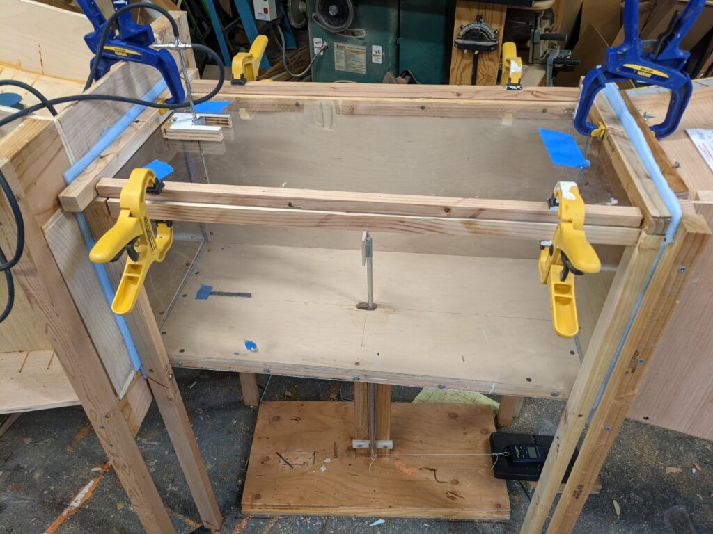
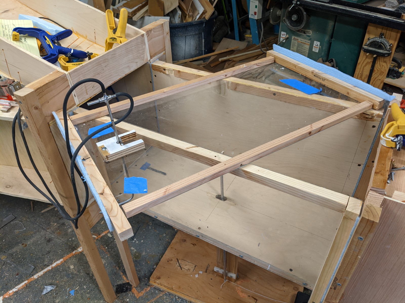
The Test Section is the area in which the model under study is actually placed. On my tunnel, it is 13.5 by 13.5 inches square, and about 30 inches long. It has a plexiglass front and top, and the top is made for easy removal to install models. The simple apparatus to measure forces on the model is under the test section.
The blower is located downstream from the test section, so it pulls air through the test section. This is to avoid turbulence from the blower from impacting the test section. The blower must provide sufficient airflow over the pressure drop of the tunnel to achieve the velocities you want to test.
Upstream of the test section is a contraction section. Its purpose is to pull ambient air in from a relatively large area at a low speed. The contraction section accelerates the air smoothly into the test section. The entrance to the contraction is about 6 times the area of the test section. There is an egg crate like structure at the entrance to the contraction which reduces lateral turbulence in the airflow.
Immediately downstream of the test section between the test section and the blower box is a diffuser, which slows the air down and recovers some of the static pressure before the air reaches the blower chamber.
On this tunnel the blower chamber is a box with the diffuser entering one side, and two furnace blowers blowing air out of the two sides of the chamber. The furnace blowers provide a way of moving quite a bit of air through the significant pressure drop of the tunnel, and are cheap to free to buy. But, they do fall somewhat short of expectations, and this is one area where advice would be appreciated (see below).
In addition to these four sections, there is drag force measuring setup that measures the drag force on the model.
Contraction Section Design and Build
The contraction section takes in ambient air at low speeds and smoothly accelerates it to the entrance of the test section.
The references suggest that the contraction section should have an about 12 degree closure angle. For this kind of low speed tunnels, a contraction inlet area about six times larger than the test section area works well. For my tunnel, the entrance is 34 by 34 inches, which is 6.3 times larger than the test section entry area of 13.5 by 13.5 inches. With the 12 degree angle, it is about 53 inches long, including a 6 inch straight section at the front to hold the flow straightener.
The contraction section works better (produces smoother airflow) if the walls are curved such that the flow into the contraction and from the contraction into the test section is tangent to the flow direction.
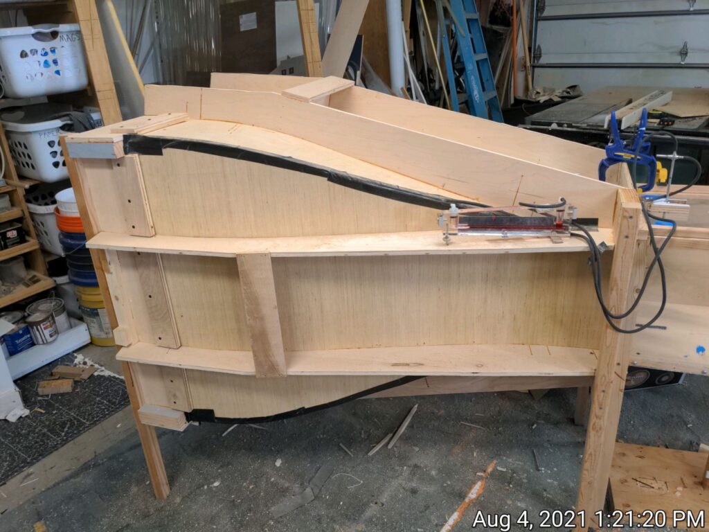
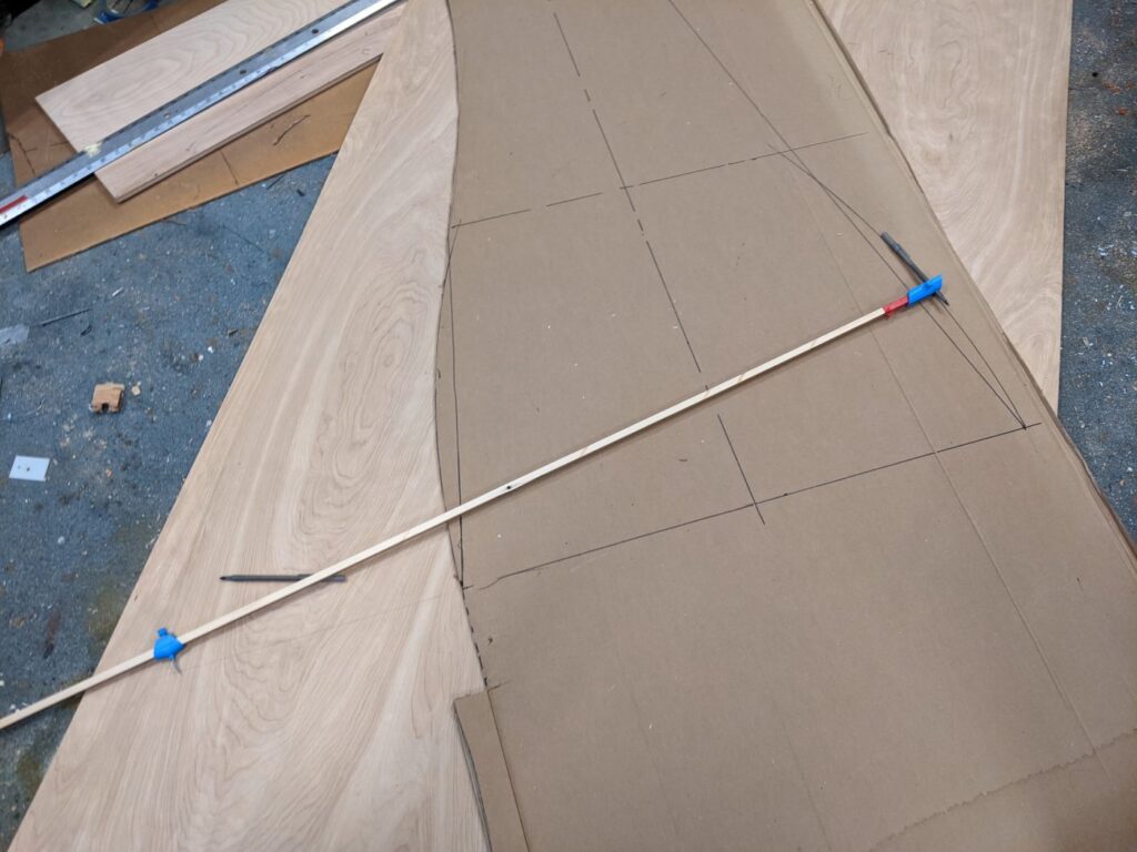
The picture above shows how the contraction was laid out on a cardboard template. The large end (contraction entry) is 34 inches, and the small end is 13.5 inches to match the test section entrance. On the cardboard template, the straight line is the recommended 12 degree contraction angle. Circular arcs are drawn with the compass (in picture) such that portion of the arc is tangent to the incoming airflow on entry, and tangent to the 12 degree line such that a few inches of the 12 degree line remain after drawing the arcs. The center of the entry arc is in line with the contraction entry plane, and the center of the exit arc is in line with the plane of the test section entry. I don’t recall the exact value of the radii of the two arcs, but its easy enough to just experiment until until they meet the above criteria.
The construction sequence I used…
- Cut out the cardboard template
- Cut out the 4 sides from 1/4 inch plywood using the template
- Cut out the 8 support frames (2 for each side) using the same cardboard template for the inside surface of each frame. Be sure to extend each frame enough to support what ever kind of flow straightener you plan to use on the front of the contraction.
- Assemble the support frames into groups of 2 (each group of 2 will support a side) – use one spacer at the test section end and another about 2/3 of the way up. Use glue and screws.
- Make a support frame for the flow straightener using half inch plywood (this will support the large end of the contraction)
- Assemble the 8 frames into their final shape. Use blocks of 2 inch lumber in the corners at the test section end, and use the square frame for the flow straightener to support the large end of the contraction frames. Use glue and screws.
- Install the plywood sides inside the frame. Use glue and screws – weights will likely be needed to hold the bent plywood in place while the glue cures. The final result will be quite strong and stiff.
- Tape the outside corners where the sides come together. Caulk the corners on the inside.
<ADD DIAGRAM>
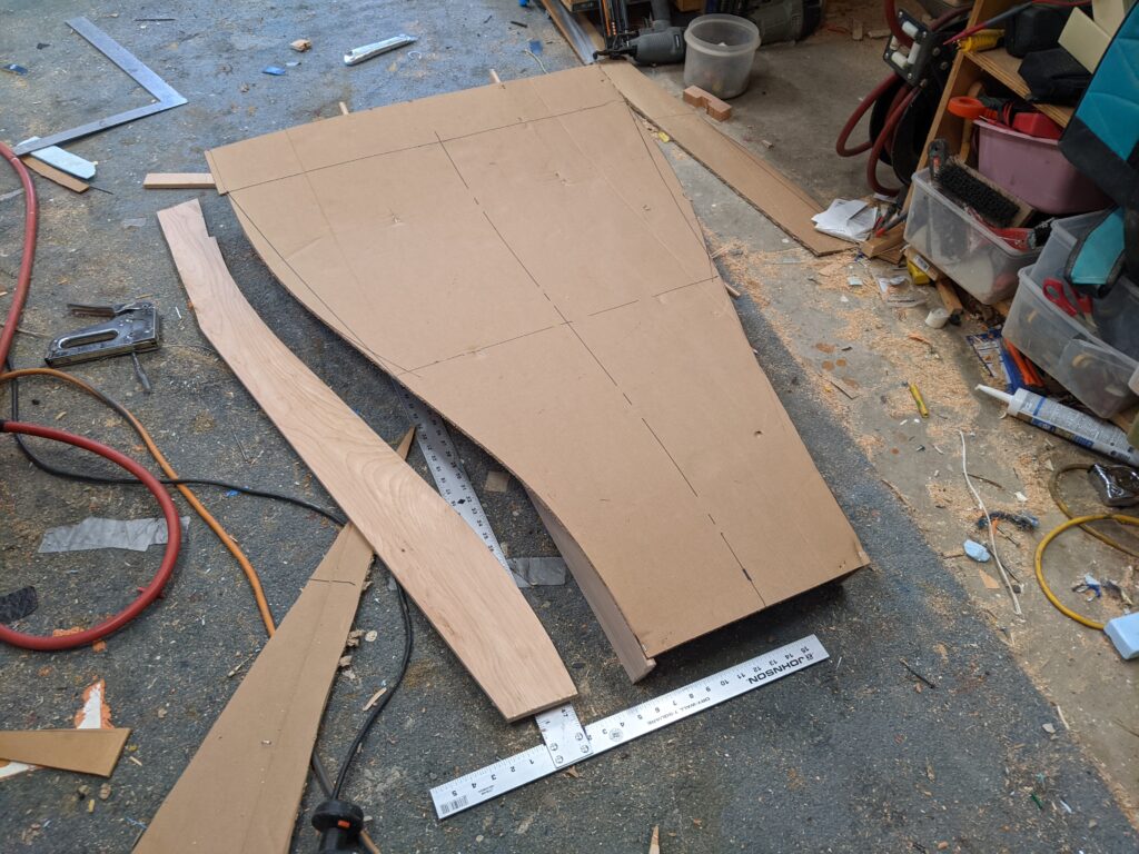
This template is then used to cut out all 4 sides, and also as a template for the curved part of the support frames. The cardboard template actually makes the construction fairly straight forward.
The sides are made from 1/4 inch plywood. It has to be flexible enough to form into the curved shapes. The frames are made from half inch plywood. It turns out to be quite rigid with all the glued joints.
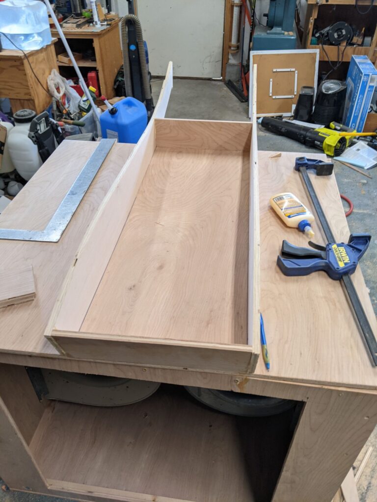
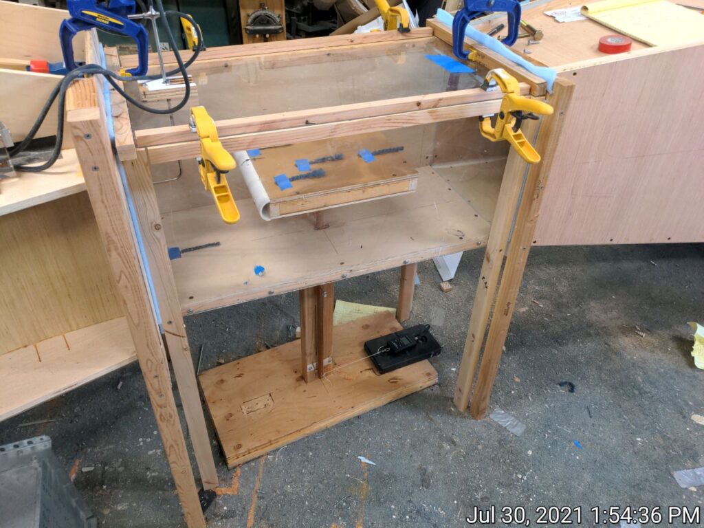
Two of the side frames assembled together.
This will support one of the four plywood sides.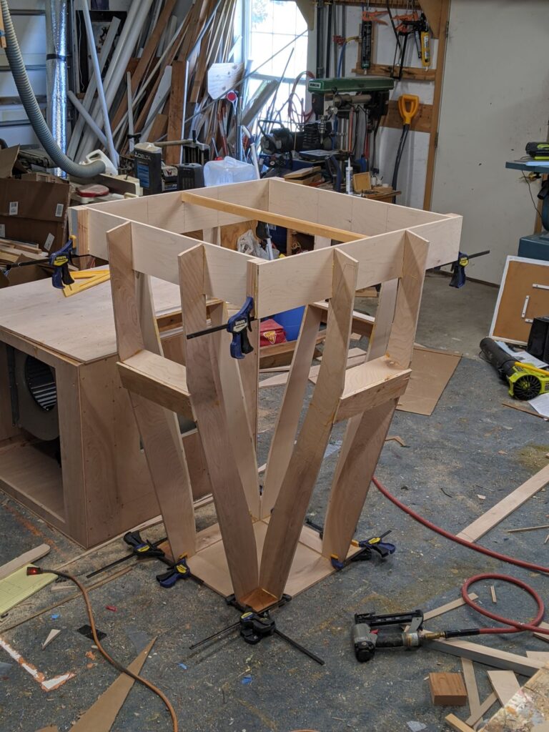
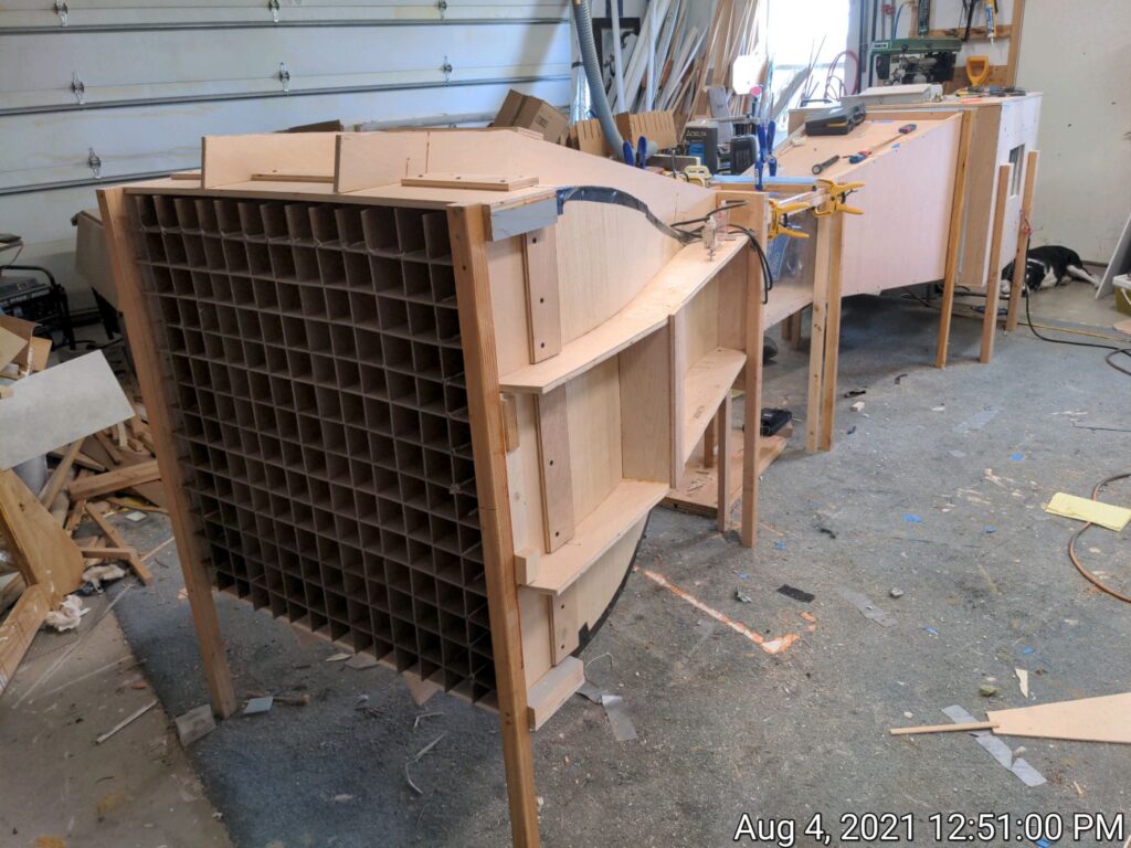
The support framework for the contraction section before the sides were installed. Note the blocks of wood at the corners of the small end that the pairs of support frames are attached to. 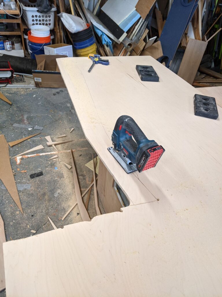
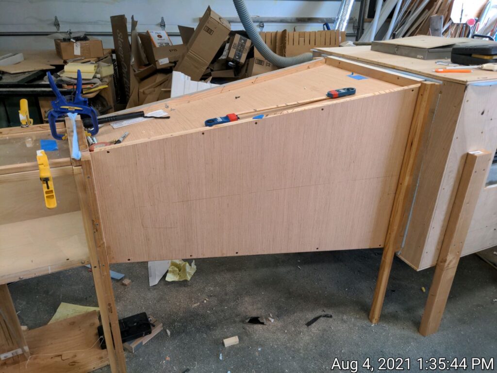
Cutting out the sides of the contraction section after tracing it from the template 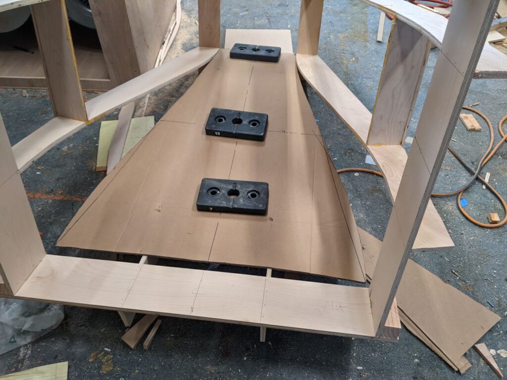
Gluing and screwing the contraction section sides to the curved support frames. The weights are holding the plywood to the frames while the glue cures. 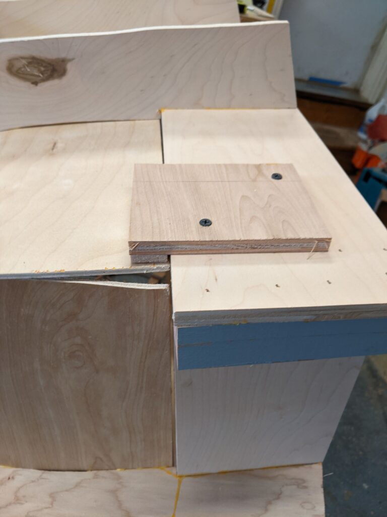
This straight section at the entry to the contraction section supports the egg crate 
Installed contraction section with the egg crate flow straightener in place

There is a straight section about 7 inches long at the large end of the contraction to support the flow straightener (see below).
After the sides have been glued in place on the support frame, the corners can be smoothed out and sealed using some tape and caulk.
While some build the contraction section as a simple, straight side pyramid, curving the walls of the contraction section so that they are 1) tangent to the incoming airflow on the inlet side, and 2) tangent to the sides of the test section on the outlet side. This makes the construction much more time consuming, but I went ahead and did it this way. The references provide an optimized curve for the walls of the contraction, but the arcs of circles I used are simple and appear to do the job well.
It would be an interesting experiment to build a contraction that is a simple pyramid and compare its performance to the curved wall design. The pyramid one could be made in a few minutes from cardboard – guess I should do this.
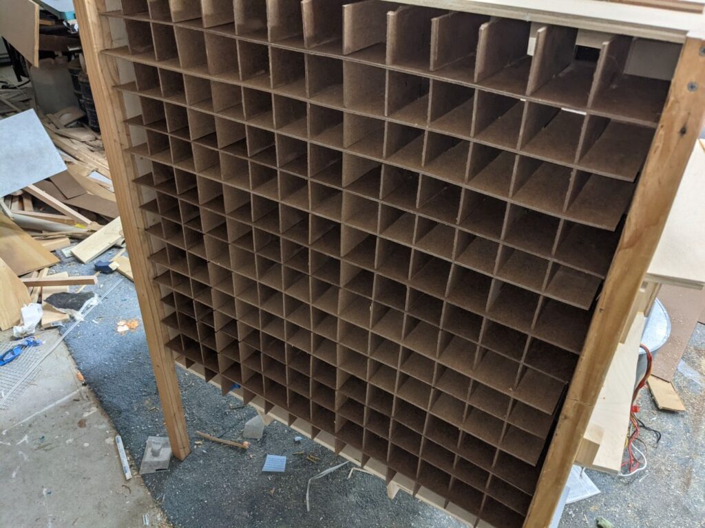
Flow Straightener: At the entry to the contraction section is egg crate like section whose function is to straighten the flow and take out turbulence acting perpendicular to the flow. On commercial tunnels, this is often made from honeycomb core, but this is not so easy to come by and not inexpensive. Some small tunnels use plastic drinking straws, but for my size tunnel, this would require about 20,000 straws that would have to be cut to length and then painstakingly secured in place – this just did not seem practical. I ended up making the flow straightener from 1/8 inch hardboard.
The design guidelines for the flow straightener are that the size of the individual cells is not so important, but to do the flow straightening, the length of the cells should be about five to size times the cell size. My straightener has about 2.1 inch square cells, so it should be about 10 inches long. Mine are only 7 inches long, but do appear to do the job well. It is also important not to have the flow straightener block block too much of the flow area – not more than 10% is given as a guideline. My hardboard is just about 9% – it ends up causing very little velocity reduction in the test section. But, using a thinner material than hardboard would be better.
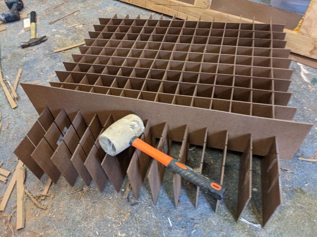
I did have a go at making the egg crate out of cardboard, but could not get it to keep its shape. This seems like a good way to go, and maybe with the right cardboard, it could work well.
Judging by the behavior of yarn tufts taped to the tunnel walls, the egg crate does reduce lateral turbulence and does appear to be worthwhile to install. When I add smoke for flow visualization, it will be a real test of how turbulence free the airstream is.
Many tunnels also have screens installed to reduce turbulence in the direction of the flow. For the testing I was doing, it did not seem worth the effort to reduce the small variations in velocity, so I did not install screens. This may change when I try to install a smoke system later.
Test Section Design and Build
The test section is the area you put the model in to observe flow around it and measure forces on it. It should have the following characteristics:
- Uniform air flow at the desired velocity(s)
- Sufficient size to hold the intended test models
- Low turbulence
- Transparent walls so you can see and photograph whats going on
- Removable top or side to allow installing the model
- Instrumentation to measure the air velocity
- A means to measure the forces on the model
- Support smoke streams to see the airflow around the model
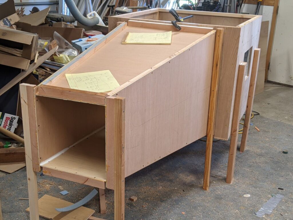
On this tunnel, the top and front sides are made from 1/8 inch plexiglass. The top is easily removable and is held in place only with hand clamps. The bottom and back side are made with half inch plywood. Solid lumber is used to frame the edges. A hole is cut in the bottom to allow the rod that supports the model to go down to the drag force measuring device. Sill sealing foam tape is used to seal the edges to reduce air leakage.

Diffuser Design and Build
The diffuser is a diverging area section between the downstream end of the test section and the fan box. It recovers some pressure to make the blower job a bit easier and probably reduces turbulence that would result in the test section dumping right into the blower box.
The test section end of the diffuser is 13.5 by 13.5 inches to match the test section, and the fan box end is 26 by 26 inches. The diffuser is 48 inches long – part of the significance of this dimension being that it economizes on what is very pricey plywood these days. The divergence angle works out to 7.4 degrees, which is pretty close to the recommended 7 degrees.
The diffuser is made from 1/4 inch plywood with about 1 by 1 inch solid lumber corner and end reinforcements. The corner reinforcements are placed outside the diffuser to keep the contour inside from having bumps in the corners. To do this, two of the sides must be extended a couple inches to provide a place to glue the corner reinforcements on.
The solid lumber to frame the ends of the diffuser has to be ripped at a 7 degree angle in order to be parallel to the test section and fan box.
Foam sill sealing tape is used to seal each end to reduce air leakage. Caulking is used to seal the inside corners of the diffuser.
When operating at 40 MPH, the static pressure at the upstream end of the diffuser is -0.61 inches of water, and at the downstream end of the diffuser its -0.36 inches of water, so there is some recovery.
Diffuser from test section end.
Caulking is to smooth and seal corners.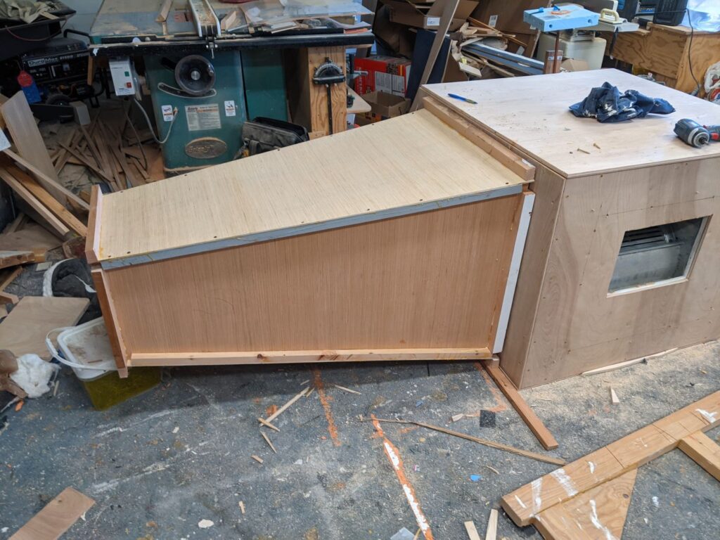

Blower Box Design and Build
The blower is located downstream of the test section and pulls air through it at the required velocity. The blower is normally installed downstream of the test section so that blower turbulence does not effect the test section.
Probably the biggest challenge in building a hobby wind tunnel of this size is finding a blower that can provide the required flow with the fairly large pressure drop through the wind tunnel. I’m still looking through a better solution for the blower.
For now, I am using two furnace blowers mounted in a plywood box. The test section connects to the blower box via a diffuser, and the furnace blowers pull air out of the diffuser and exhaust it out the sides of the box. This works fairly well, but the two blowers only provide enough flow to get the test section up to 40 MPH, and I would like to see 60 MPH (or more).
The furnace blower motors do have some advantages: 1) they are available for free from furnace pullouts at HAVC dealers, 2) they are usually 4 speed blowers, so some variation in velocity is available, 3) they are capable of working with the fairly high pressure drop through the tunnel.
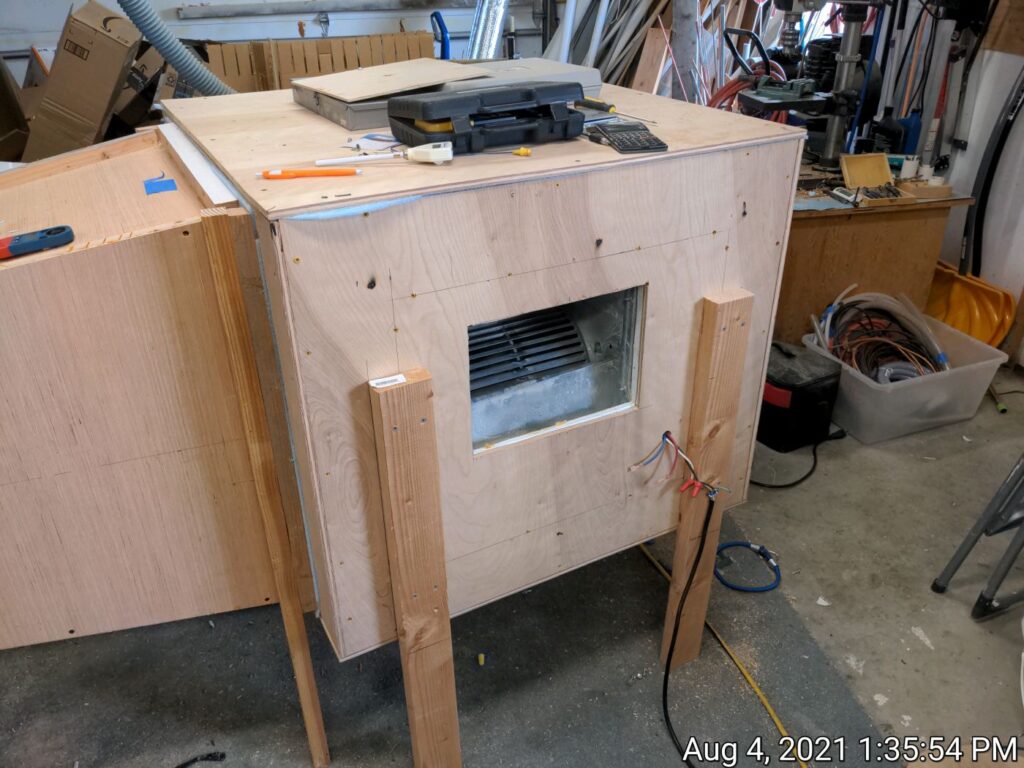
The blower box is made from half inch plywood with solid lumber corner reinforcements. The box is glued and screwed together with the top easily removable for access. A large hole on the upstream side is cut for the diffuser, and cutouts are made on opposite sides for the furnace blower exits. The pictures show the construction.
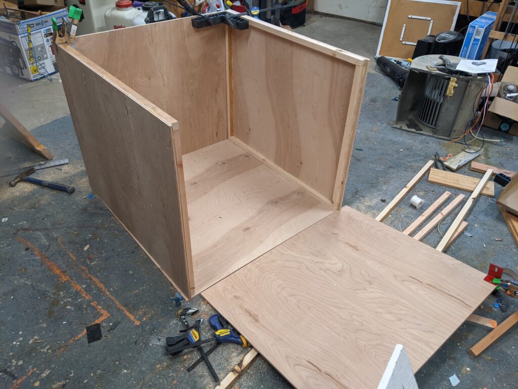
Building the box from half inch plywood with lumber corner reinforcements. 
The completed box with the top screwed down. A sill seal foam band is used to seal the top to the box base. 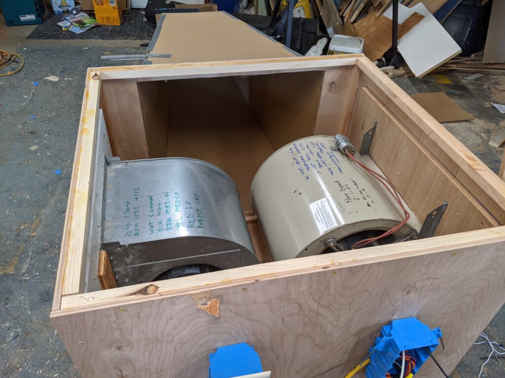
The two furnace blowers mounted inside the box. 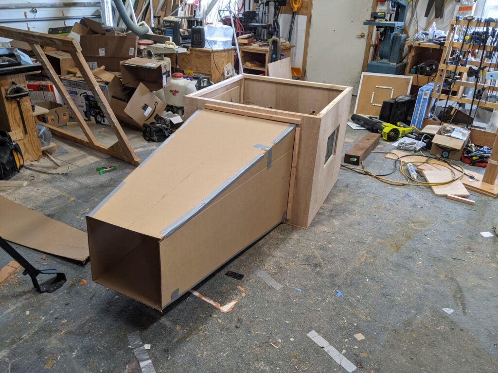
The completed box with the top off. A mock-up diffuser has been attached. 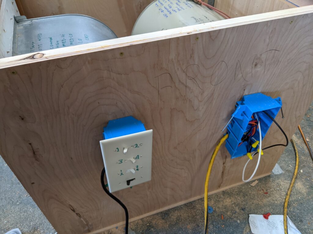
This arrangement of switches allows each blower to be run at one of 4 speeds. 
A done with the box beer.
The box is 36 inches wide by 36 deep by 30.5 high. The basic construction is half inch plywood with half inch plywood doublers reinforcing the blower installations.
In the wiring, each of the two blowers is hooked up independently with its own multi way switch. The blowers normally have four speeds with each speed having its own wire. In addition, there is a normally white common wire. The lowest switch on the box turns off all power. The next switch up selects either speeds 1 and 2, or speeds 3 and 4. The upper switches are three way switches that select speed 1 or speed 2 (upper) or speed 3 or speed 4 (2nd one down). It would be nice to have a fancy 4 way rotary switch, but this arrangement uses only cheap HomeDepot switches, which were, mostly in my junk box. The wiring arrangement is shown in detail on this blower door project…
Force Measurement
At this point, I am only interested in measuring drag forces. I have used a VERY simple system to do this.
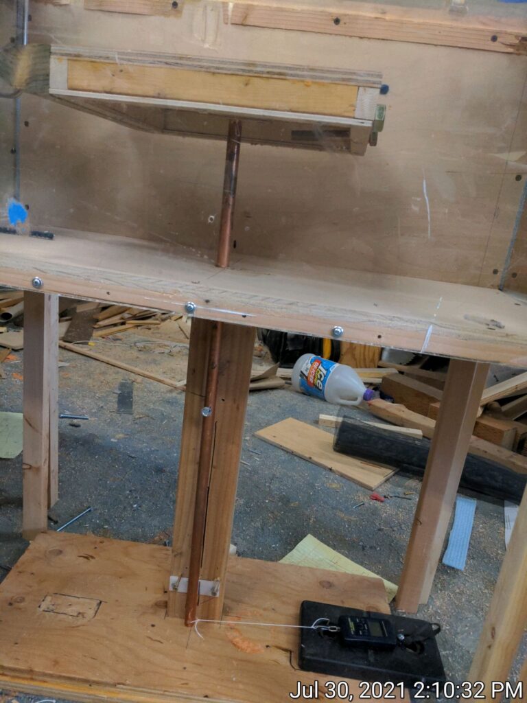
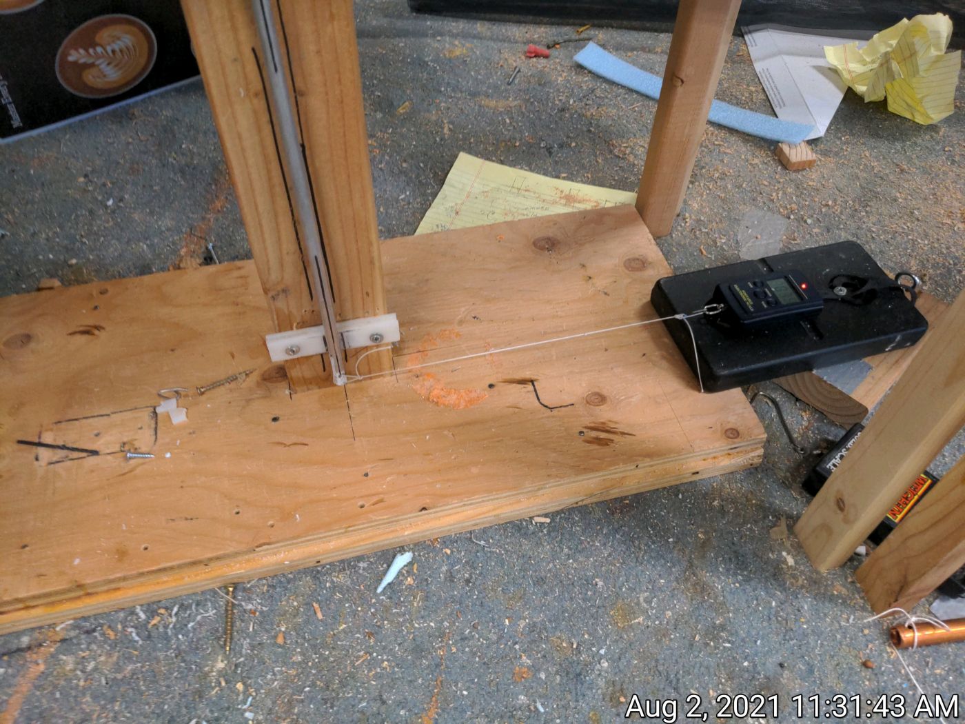
There is thin metal rod with the model under test rigidly attached to the top of the rod. The rod extends down through and opening in the bottom of the test section and extends downward to a pivot point about 15 inches below the model. The pivot is very free to turn with very little friction. The rod continues downward for another 15 inches below the pivot. So, when a drag force is applied to the model, and opposite force of the same magnitude is produced at the bottom of the rod. To measure the force, a string attaches the bottom of the rod to a digital fish scale with a resolution of 0.01 lbs.
To make a measurement, the model is mounted to the rod, the rod installed through the bottom of the tunnel, the pin is inserted in the pivot. The rod is aligned to a perfect vertical position by pulling it into place with the digital scale and the string. The tunnel is turned on, and the digital scale is used to register the force on the bottom of the rod (which is identical to the force on the model).
In addition, the model itself is balanced such that the CG is over the rod.
A run is done with just the bare rod in place (no model) and the force that is registered for the bare rod is subtracted from all of the model readings.
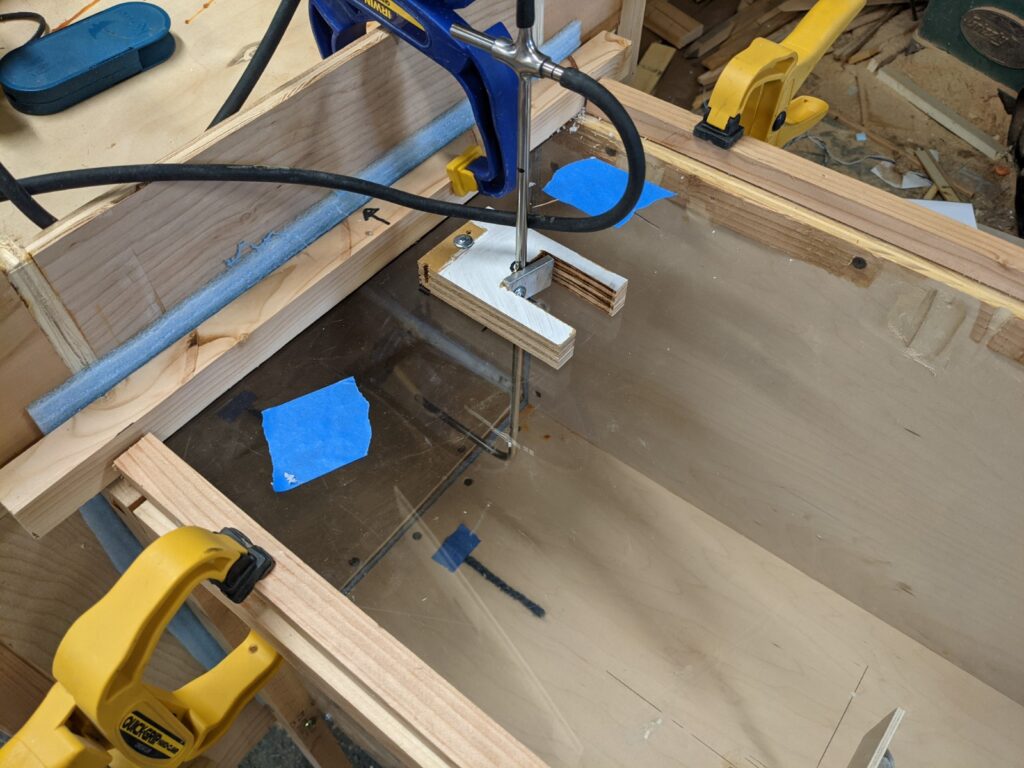
Model connected rigidly to the rod.
Pivot in rod is visible about 6 inches below the bottom of the test section.
The string and scale are visible at bottom of picture.
Bottom of the rod is connected with string to digital scale.
The rod is perfectly vertical when force is measured.
Supports
Something is needed to bring the support the tunnel level and at a convenient working height. I also wanted the 4 main sections of the tunnel to be easily disconnected from each other so they could be moved to the barn where this thing will eventually live. I just added some simple wood legs to each section to support it inline with the other sections. I also used foam sill seal tape between each section to reduce air leakage. You can see the added legs in some of the pictures above.
Testing
I have done a little testing on the tunnel, the results of which on this page… <ADD TESTING PAGE>
Performance
I guess you can grade a wind tunnel on two main things: 1) uniform velocity across the test section, and 2) low turbulence in the test section.
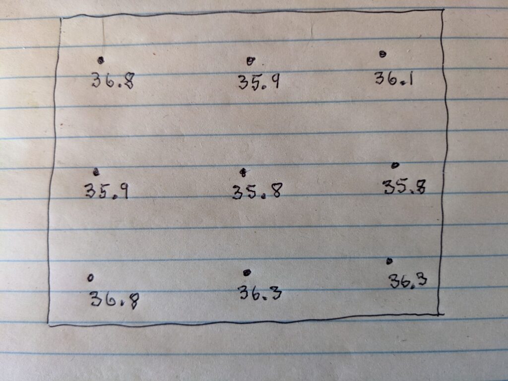
Using a pitot tube and a Kestral anemometer, this is a survey of the velocities in the test section.
It shows the velocity in MPH at nine locations across the 13.5 by 13.5 inch test section.
A pitot tube connected to a very nice, old Dwyer tilted oil manometer is used to measure airstream velocity. The pressure read from the manometer is converted to airstream velocity. The air density enters into the calculation, and since I am at 5000 ft elevation I have to correct for the reduced air density.
I also cross check with a Kestrel anemometer. I like the Kestrel because they are calibrated as a part of the manufacturing process. The pitot tube and anemometer readings agree well — normally within a or 2 MPH.
Pitot tube to measure airstream velocity 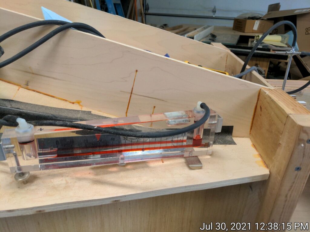
Dwyer tilted oil manometer to read pitot tube pressure
Good enough for engineering work 🙂
The only way I have to measure turbulence in the test section is with yarn tufts on the walls. With the flow straightener in place and the tunnel at its highest speed, the tufts are very still – so, at least by this measure, the turbulence level is low. I plan to add smoke visualization later, and this will be a further test of turbulence levels.
Cost
This was a low budget project.
I had most of the wood on hand except for a couple sheets of half inch plywood (painful to buy these days) and a couple sheets of hardboard. The furnace blower motors can usually be had for free from furnaces being replaced by HVAC dealers. I had all of the instrumentation from other projects. Maybe a bit over $100 for the whole thing.
References
A list of some articles, books and videos that I found helpful for the design.
<REFERENCES>
Questions and Challenges
There are a couple issues I’m still wanting to resolve – any help would be appreciated…
Blower: The highest test section speed I’ve been able to achieve is about 40 MPH (4430 CFM)- I would like to be able to get up to about 60 MPH. 60 MPH through the test section would require an actual flow of about 6650 CFM. The furnace blowers are rated at about 2500 CFM, each and are actually delivering about 2200 CFM each, so, fairly close to their rated output. These blowers are able to operate with the fairly large pressure drop through the tunnel.
I have tried adding a 12 volt car radiator fan that was rated at 3000 CFM and it appeared from what little specs were available that it could work against some pressure drop, but while it did produce roughly 3000 CFM in free air, its performance when hooked to the tunnel with the two furnace blowers was dismal. Reinforcement of the message that the fan/blower must be capable of producing flow through a significant pressure drop.
I could add a third furnace blower, and this would get me close to 60 MPH, but if anyone has any ideas for another arrangement that won’t break the bank, I’m all ears. Ideally about 7000 CFM when operating with a pressure drop of about 1 inch of water would be good.
Validating: For the work done so far, the drag coefficients calculated for the models seem high compared to what I would expect from handbooks.
One way to check if the drag forces measured in the wind tunnel make sense is to use the measure drag force, frontal area, and airstream velocity and use it to calculate the drag coefficient, then compare the calculated Cd to what the references say Cd should be.
The equation for drag is:
D = 0.5 * d * V^2 * Cd * A
where
D = drag force in lbs
d = air density in slugs/cubic ft
V = air velocity in ft/sec
Cd = drag coefficient
A = frontal area in square ft
Solving for Cd
Cd = D / (0.5 * d * V^2 * A)
I made a square flat plate and measured the drag force on it, and then back calculated the drag coefficient using the formula just above. The flat plate was 2 3/32 by 2 3/32 inches square (0.030 sqft), Velocity = 52.9 ft/sec (36.1 MPH), d = 0.065 lb/ft^3 (0.0020 slugs/ft^3),and the measured drag force was 0.17 lb.
Plugging these values into the Cd equation
Cd = 0.17 / (0.5 * 0.0020 * 52.9^2 * 0.03) = 2.02
The handbook Cd values for flat plates are around 1.3.
So, this is bothersome that there is such a large discrepancy. If you have any theories on what might be causing this, please let me know.
References
<ADD REFS>
Hello,
I’m not an expert, but maybe if you converted it into a closed-loop wind tunnel, the efficiency would increase significantly and the blowers would have an easier time. Because you don’t have to re-inject the air every time, you only have to deal with the internal resistance of the closed pipe network. I don’t know if it’s a good idea, but consider it. Of course it would heat up and you can’t use smoke…
Greetings: Andor Szabó
Hungary, Budapest
it is said that a 30-40% efficiency improvement can result and thus a smaller turbine is needed, or the existing one will have an easier time
Hi,
Thanks Szabo.
I did think about a closed circuit design when I first started thinking about building the tunnel, and decided against it just do to the extra material and work, but maybe its time to think about it again.
Gary
Hi,
An other solution is the water tunel… 🙂 Slow speed, better turbulent visualization…
For your drag measurement, I would try it with a model that has a greater frontal area. The model you are using seems to be very skinny (top to bottom) and it also looks like the bottom is not closed. This would allow the air to recirculate behind the front face and that could change the drag significantly. I would try the following two things:
1. Create a model with a greater frontal area. Make sure that the blockage w.r.t. to the test section’s cross-sectional area is not more than 10%.
2. Close the bottom of the model and have the rod mount through a hole in the bottom. If making a model like this is difficult (w.r.t. mounting to your balance), you can close the bottom off using Ceran wrap or something like that.
Calibrate the balance with a known weight so that you know what you are reading is reasonably accurate.
Thanks for the suggestions.
Gary
Very nice work! Did you solve your blower problem and get the velocity in the test section beyond 40 mph?
Hi Kisambi,
Thanks.
Not much has happened since the write up above.
Hoping to get back to it in the summer.
If you (or anyone) has ideas on getting the velocity up, I’m all ears – I’d raise the budget up to $1000 ish for a good solution!
Gary
I think your best bet to get the velocity up is to increase the flow rate. With the flow rate you are getting, you are pretty much maxing out the two blowers you have. Given the size of your test section, that is the best you can do. If you do not want to add additional blowers, you’ll have to upgrade the capacity of the blowers. However, that will increase the size of the fan box and that may not be something you want to do.
If you have the room for it, I would add 2 more blowers, one blowing out the top and the other out of the bottom so that you can increase your flow rate and thus your velocity through the test section.
Another option I thought of would be to change the shape of the inflow section so that you are reducing losses. However, you are getting fairly close to the expected velocity in the test section, so the blowers have enough capacity to overcome the head loss through the tunnel, so there is not much point in redoing that. That is going to cost you time and money and I think it would be better spent on adding the additional blowers.
Harry,
Nice work! I have a few suggestions for you. First, add some bellmouth-like shaping at the inlet to your tunnel, perhaps a, elliptic shape or circular radius of 3-4″ all the way around the perimeter (see http://www.profblairandassociates.com/pdfs/RET_Bellmouth_Sept.pdf). This will pull air in gently without having a bunch of dirty air (separated flow) along the walls. Second, be very meticulous in dealing with your weight balance. Calibrate it with a known force in the drag direction. Maybe add high quality bearings in your pivot or do other things to minimize friction. At 40 mph drag forces can be very tiny. Thank you.
As far as the Cd calculation – this is a complicated area and my experience in this area is ~ 40 years out of date.
The people who really know what they are doing use much more sophisticated algorithms and computations than a linear algebra approach.
Just as a simple example:
https://en.wikipedia.org/wiki/Computational_fluid_dynamics
Most of my own calculations were done using based on Reynolds number approaches as it was more chemical engineering / pipe flow oriented. Something like this, which may or may not apply:
https://en.wikipedia.org/wiki/Reynolds_number
The big picture version of all of this is summarized in this diagram:
https://en.wikipedia.org/wiki/Reynolds_number#/media/File:Moody_EN.svg
Look at how rapidly the Re number varies with just small changes in laminar vs turbulent flow, and across relatively modest differences in surface texture.
By modern standards and of course in the aerospace industry these calculations can be quite accurate. In the 1980s / Chemical Engineering, we were happy to be in the right order of magnitude.
Very nice work Gary.
I have not looked carefully at furnace blower pressure / flow curves but typically the limitation is pressure drop.
Since you have access to those fairly inexpensively, one possible approach is to make a 2 stage design. As an example have the 2 existing blowers, each feeding into a second stage that has 2 blowers in parallel. (4 blowers in the second stage)
As a first cut estimate, this could potentially double the pressure drop in the system.