This is a followup to an earlier page looking at the heat loss due to metal frames and ribs in the van that were not insulated. Probably best to read the earlier page first if your have not already.
This page looks at a couple techniques for adding insulation to the frames and ribs to reduce the thermal bridging. The two methods tried …
- Fill the frames and rib cavities with Thinsulate.
- Apply a thin layer of foam over the metal frame or rib before paneling.
The idea is to fill the frame cavity with the Thinsulate both to provide some insulation and to reduce airflow through the frame cavity.
The thin foam is applied over the bare metal of the frame on the inside surface. This adds insulation in series with the thermal bridge created by the frame or rib.
Setup
The thermal images were taken with a FLIR I7.
Interior and exterior air temperatures were logged through test with an Onset Computer logger — logging outside temperature, and interior temps at ceiling, counter top height, and just above the floor (see plot below).
The outside temperature varied from about 36F at the start to about 34F at the end.
The van was heated by an electric space heater to provide more consistent interior temperatures than the van’s propane furnace. The space heater was left on full time and its full output was just sufficient to keep the van interior around 70F. I ran it for 3 hours before starting the test to stabilize interior temperatures. This reduced the variation in van temperature between the tests, but did not completely eliminate it.
The day was overcast, so any effects of direct sun on the van were minimal.
The wind was light.
I did run the full test twice — the results here are for the 2nd run, but the first run results were similar.
Thinsulate
The Thinsulate for the test was provided by Hein at Impact Products — thanks! It is made by 3M and the product is SM600L — its about 1 5/8 inch thick and has an R value of 5.2. The Thinsulate is a bonded to a sturdy scrim sheet.
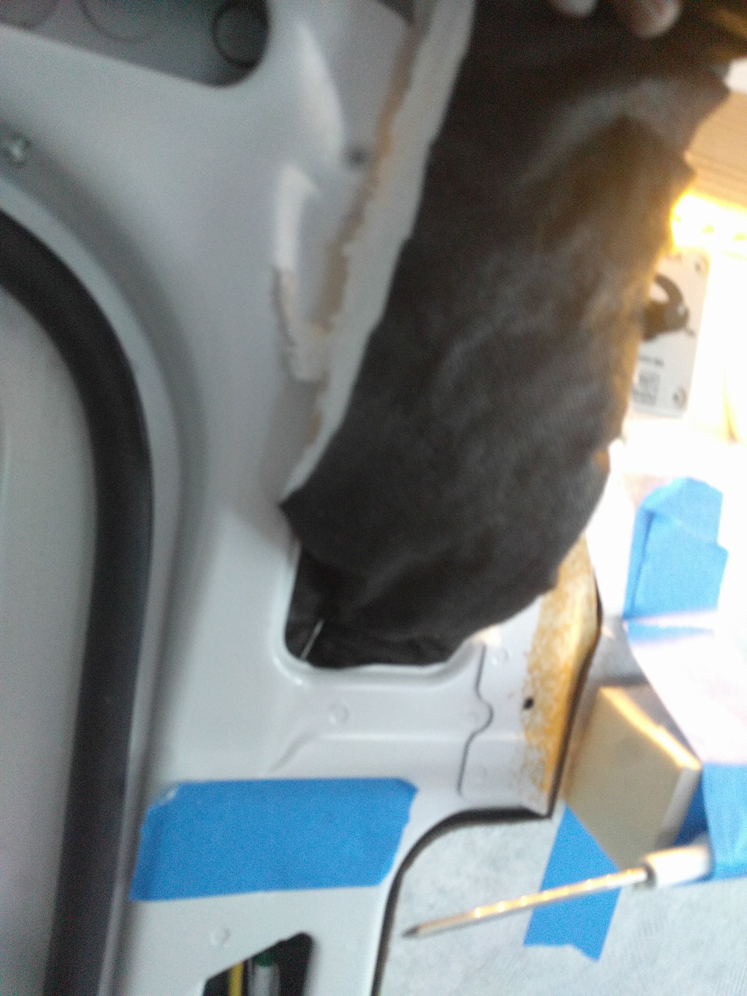
To install the Thinsulate, I ran a fairly stiff wire through the frame cavity first, then poked a hole in the strip of Thinsulate and pulled the Thinsulate through the frame using the wire. Pretty easy. The ceiling rib was a little harder as its not very deep, but not too bad.
The PM has a solid web in the frame at about bed level. I filled the frame both above and below this web with Thinsulate.
Foam
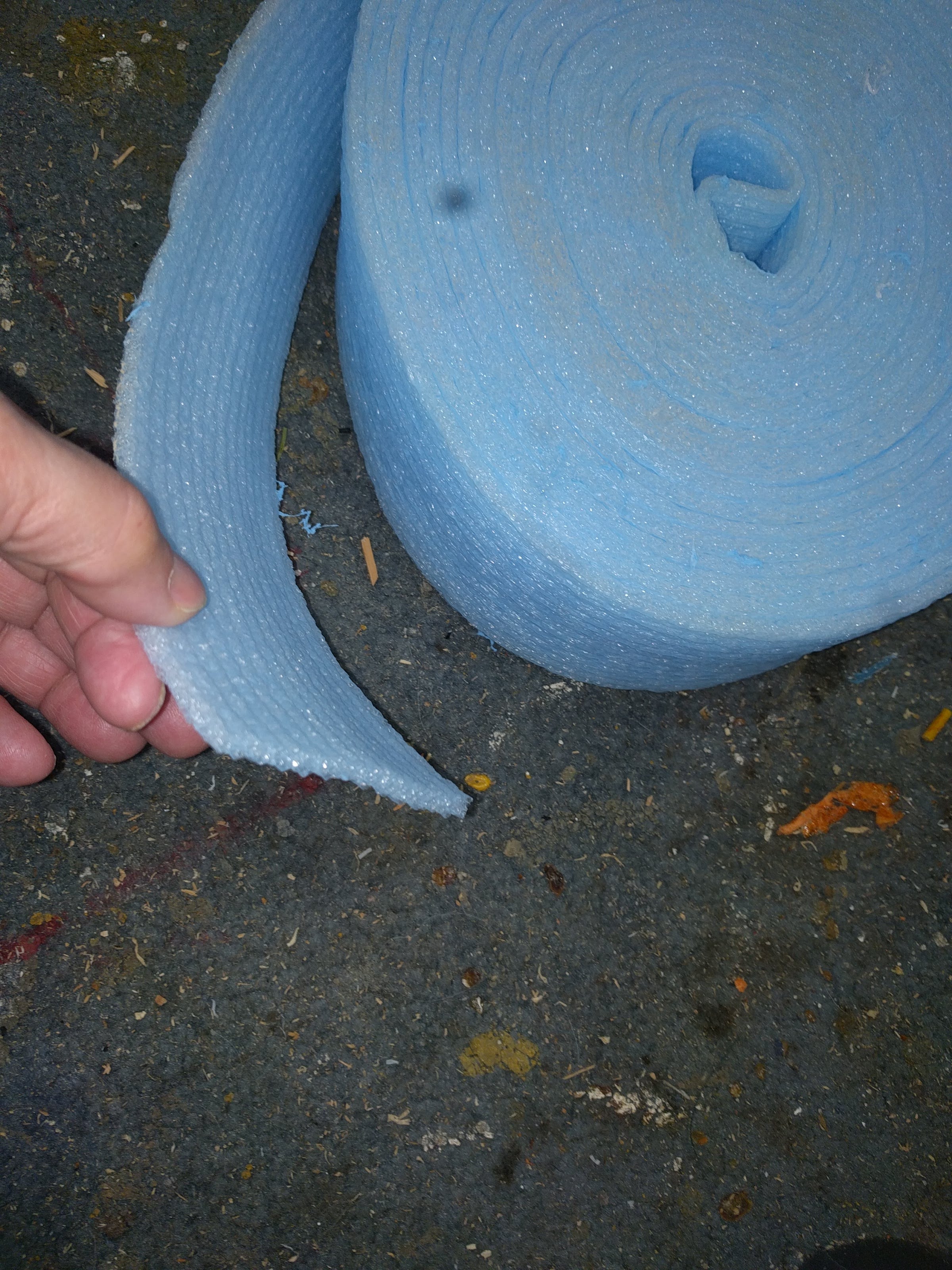
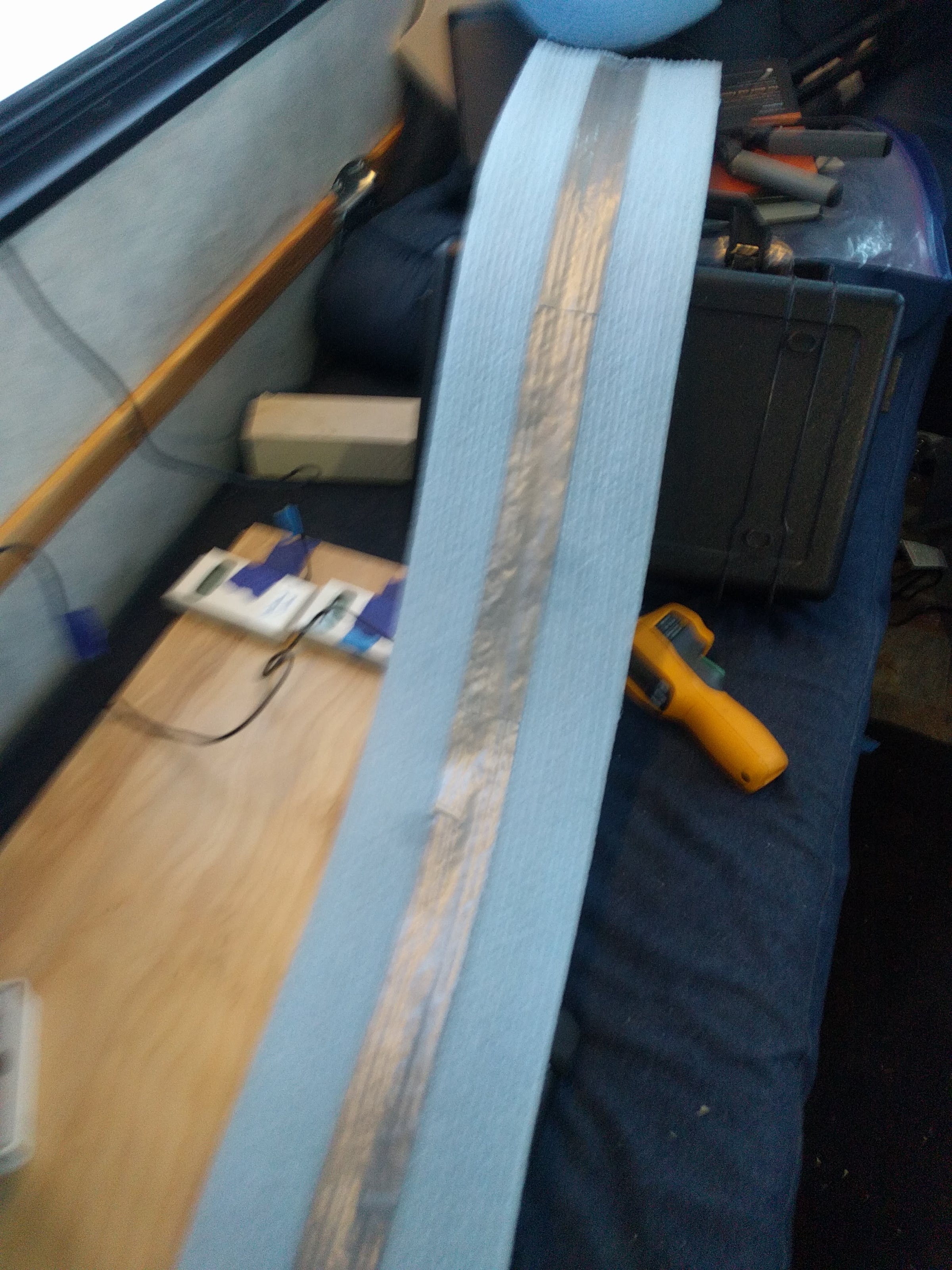
The foam I used is actually the left over seal strip that I used to seal the sill board on my shop building to the concrete slab. Its about 4 inches wide and about 1/4 inch thick. It was adhered with several strips of very tenacious double sided tape. It looks like its made from polyethylene. It probably would have been better to use thin rigid insulating foam board, but the sill sealer is what I had on hand. Something like the fan fold XPS insulation or half inch Polyiso would probably be a better choice.
Air Currents
One theory for why the Thinsulate might be effective in reducing heat loss is that it would stop the air current that would be thermosyphoned down the open frame cavity. In order to get some idea what this air current was like with and without the Thinsulate, I used this Dwyer Vaneometer to measure the air velocity near the bottom of the frame. Its a really nice gadget for measuring very small air velocities that I’ve used a lot for thermosyphon solar air heating collectors — only $25. It can measure air velocities down to about 5 ft/min, which is really slow (0.06 mph).
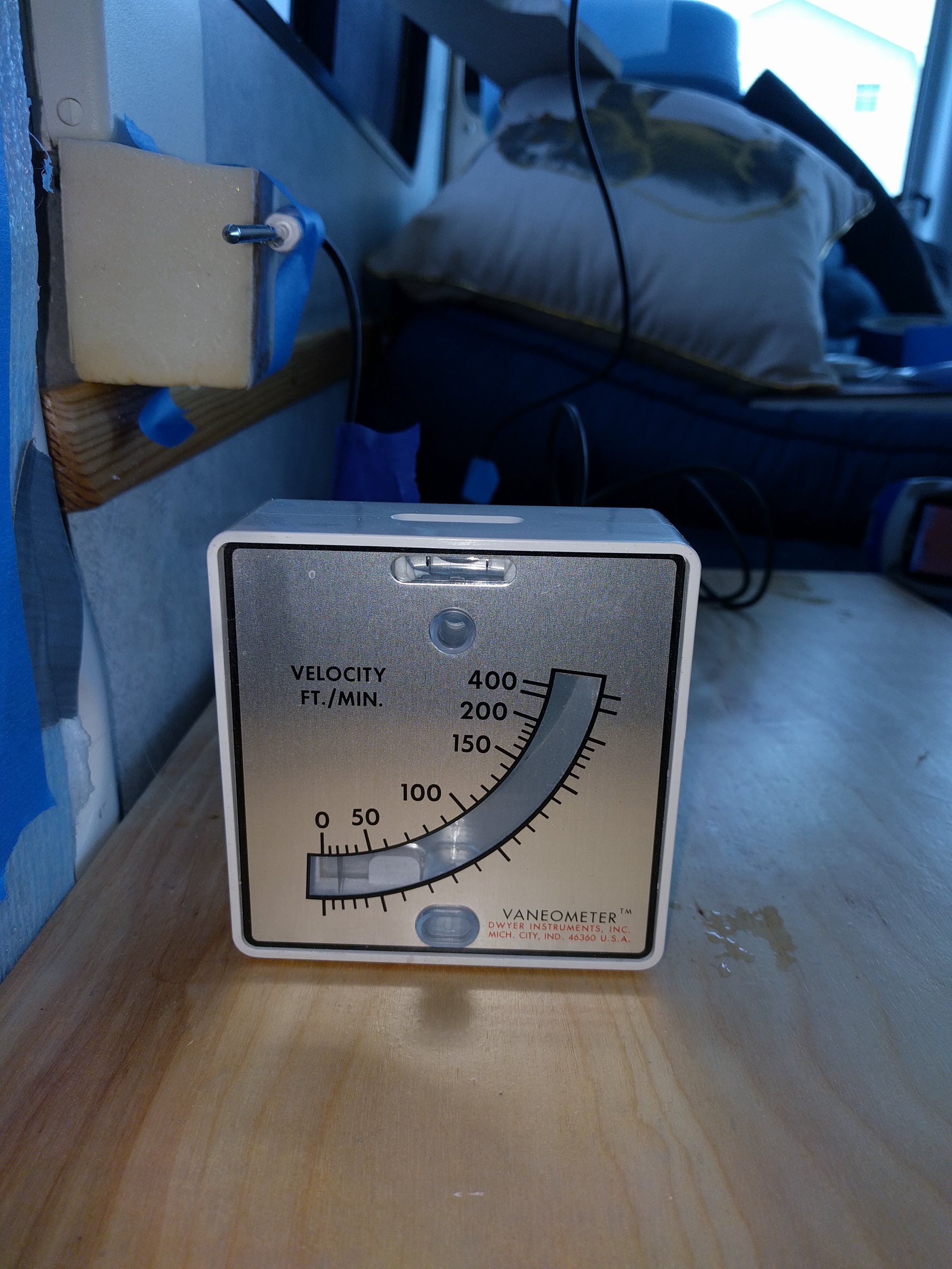
A thin plastic vane on a pivot at the top left is deflected by the airstream. The down side is that it can only measure horizontal air velocity, so the shelf is positioned to deflect the vertical air current along the frame to horizontal. The shelf is positioned just below the solid web in the frame that blocks downward airflow — idea being that such flow will be diverted outward to the meter.
The Frame
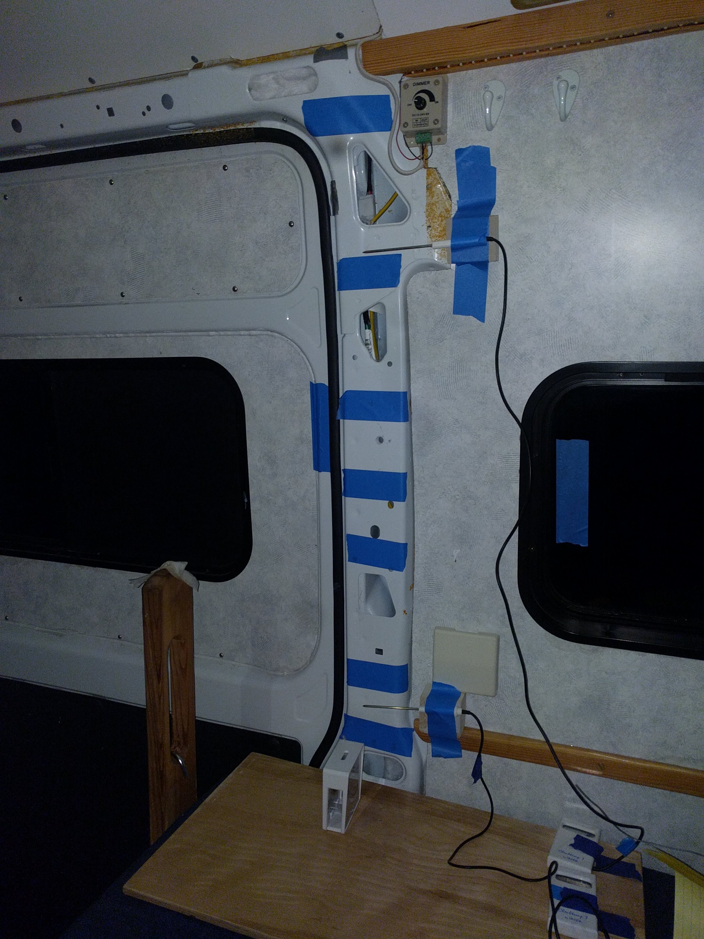
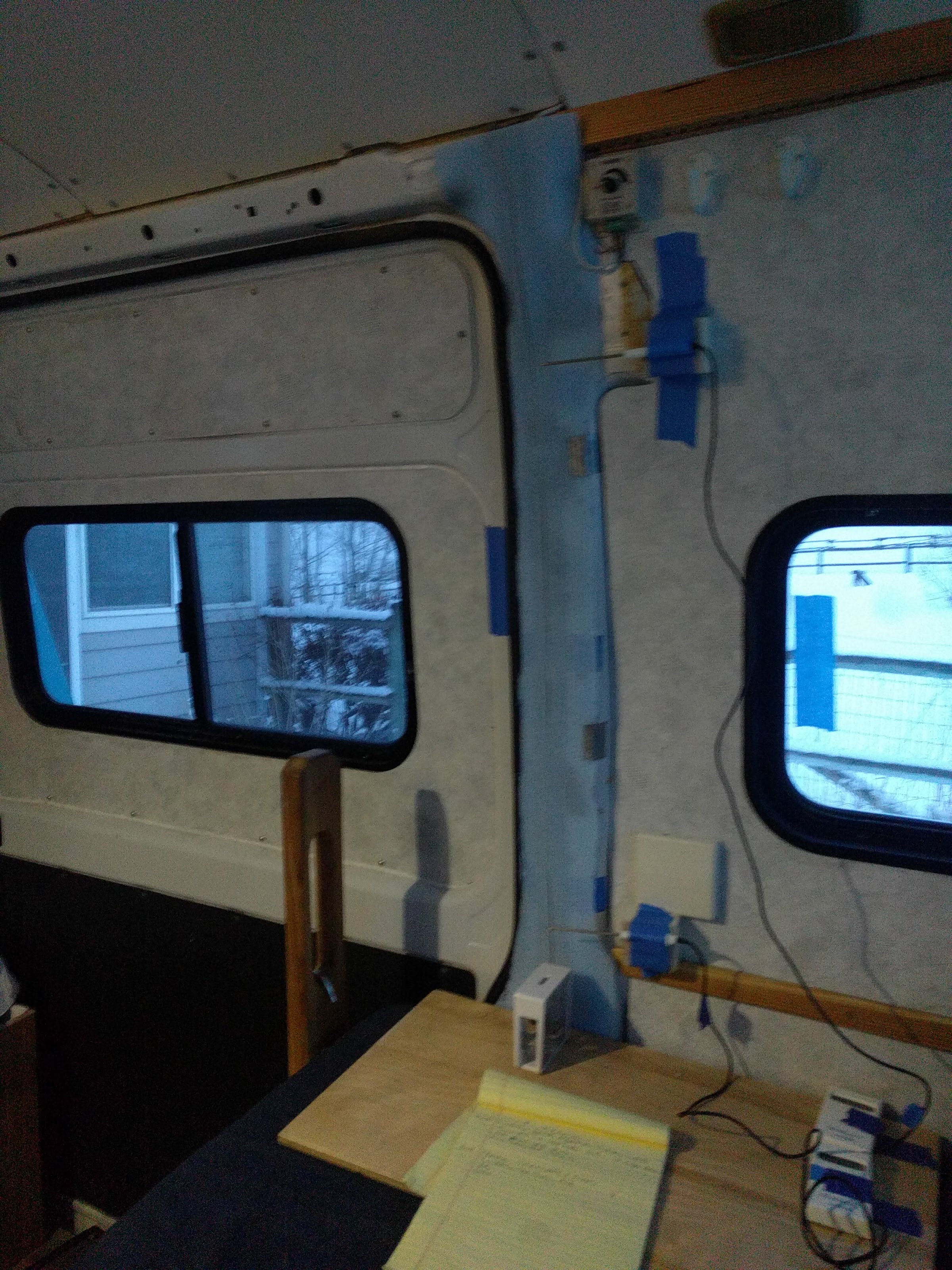
The frame I used is the one on the passenger side just behind the sliding door. I used this one instead of the one on the driver side because the driver side one had LOTS of wires running through it.

The painters tape is a check a check to make sure the frame material has an emissivity close to 0.95, which is what the camera is expecting. The painters tape does have an emissivity of 0.95, so if you can’t see it on the IR pictures the underlying material also has an emissivity near 0.95.
Conditions
The tests were all done the same day over a period of about 1.5 hours.
I let the space heater run for three hours in the van so that temperatures were stable. I waited about 15 minutes between each test to give the temperatures time to stabilized for each new insulation condition.
This plot shows the inside and outside temperatures over the test time.
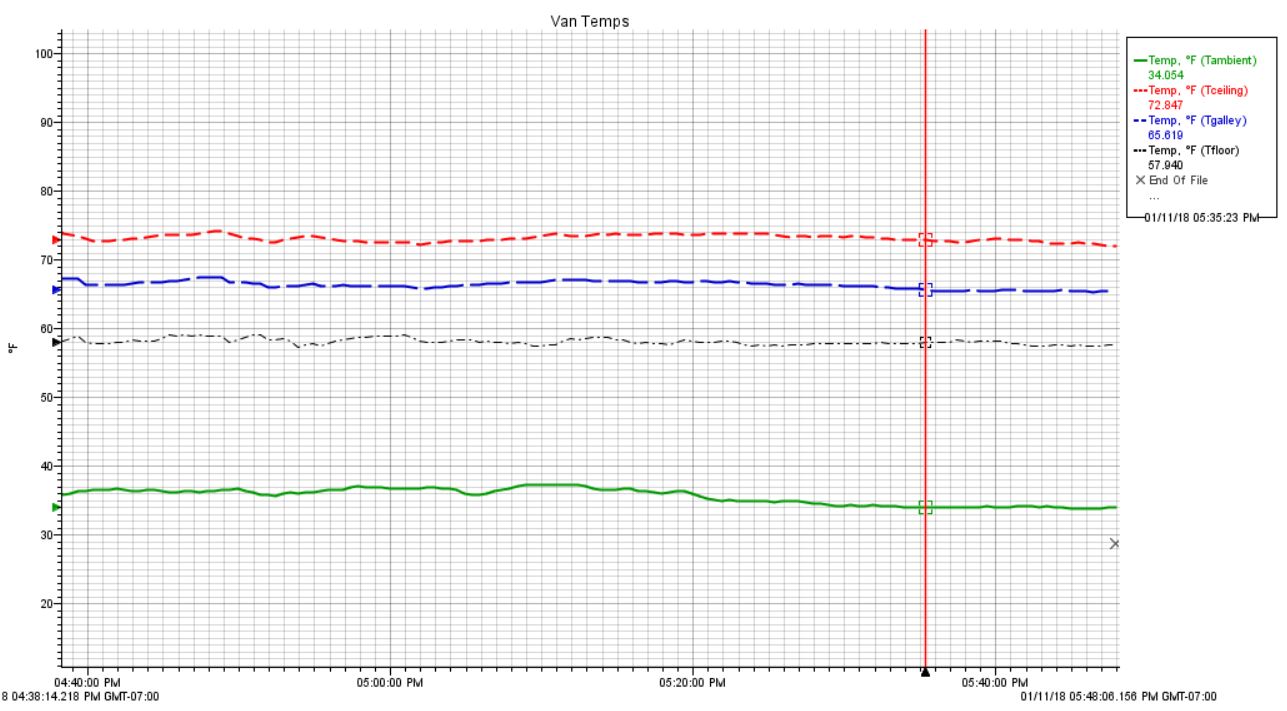
The top red line is the temperature near the ceiling (about 73F), blue line is temperature at counter top level (about 66F), and green line is outside temperature (about 34F).
The electric space heater is able to maintain an about 34 F difference between inside and outside (its a 1500 watt heater). The inside temperature trends down a bit toward the end because the outside temperature is dropping — but, the inside to outside difference remains close to 34F. Point being, conditions through the test were pretty constant.
Bare Frame Test
This is the baseline for the other tests with insulation.
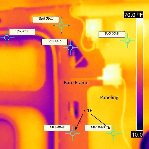
This is the IR picture of the bare metal frame before any insulation was added.
And regular picture of same…
The temperature difference between the wall paneling and the bare metal of the frame was 7.1 F. This is the baseline for the Thinsulate and foam insulation test.
The velocity of the air at the velocity meter was about 15 fpm (0.17 mph). I should mention that the velocity measured varied quite a bit. If I moved or the dog moved it might go up to 30 fpm until things settled down. Even when all was very quiet, it varied a few fpm. So, the 15 fpm in this case is an average of watching the meter for 30 seconds or so.
Thinsulate Insulated Frame
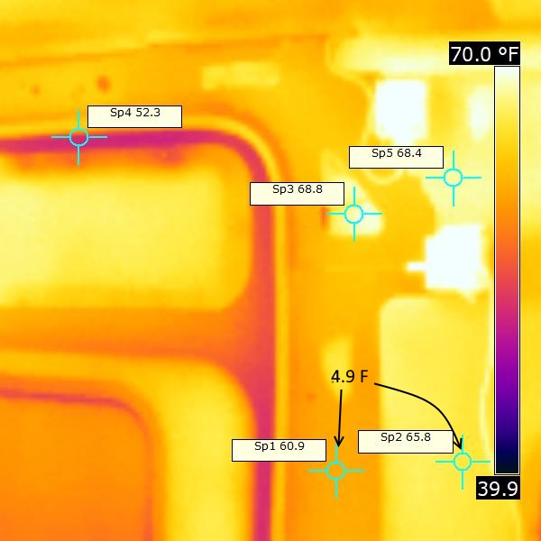
The difference in surface temperature between the insulated wall panel and frame goes from 7.1F to 4.9 F for the Thinsulate inulated frame. Anything that brings the surface temperature on the frame closer to the well insulated paneled area is a plus.
The average air velocity was about 12 fpm.
Foam Insulated Frame
This is the thermal image for the 1/4 inch foam insulation over the frame metal held in place with several lines of double stick tape.
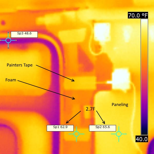
The strips of painters tape on the foam (which show up as lighter on the image) show that the foam does not have an emissivity of 0.95, which is what the camera is set for. So, the for the foam surface, the only valid temperatures are on the painters tape strips.
The difference in surface temperature between the insulated wall panel and frame goes from 7.1F to 2.7 F for the foam insulation — a good improvement in surface temperature.
The average air velocity was about 12 fpm .
Conclusions
You can look at the pictures and measurements and draw your own conclusions, but here are my thoughts…
There are things about the test that are not totally satisfying like some variation in the wall temperature even though I tried pretty hard to keep things stable. So, I would not take the results too literally. But, I’m comfortable with the following conclusions…
Heat Loss: Based on the test showing lower frame surface temperatures, I think its safe to say that both the Thinsulate and the foam reduce heat loss due to thermal bridging at the frame. Comparing the bare frame and insulated frame surface temperatures, I would say the reduction in heat loss is likely significant — maybe of the order of third to a half of the thermal bridging loss. Based on the earlier test, cutting the thermal bridging by a third to a half would decrease the total heat loss for an otherwise well insulated van by roughly 8 to 12%.
Air Currents: I’m unable to find a whole lot of difference in the air velocity between the bare frame and insulated schemes. The Thinsulate and foam do show a small reduction in air velocity, but given the difficulty in getting good readings, it may not be significant. It may be that my velocity measuring setup was not good enough to see the differences — it does make sense to me that there should be an air current down the frame and that the Thinsulate and foam should reduce it — I just could not verify it with my setup.
RD and others on the PM forum report sleeping next to the cold back wall of the van does seem colder, and the drafts might be the reason. Another possibility is that it feels colder because of radiant heat exchange between your body and the cold wall surface makes that space feel colder. Its an accepted HVAC fact that you can have two rooms with 70F air, and if one has a lower wall surface temperature than the other, it will feel colder because of the radiant heat exchange between your body and the wall. Since the added insulation did warm up the inside frame surface, it should help make the space feel warmer.
So, you have decide if the improvements due to insulating the thermal bridges are worth it. If you camp mostly in warm weather, then probably not, but its probably worth the effort for cold weather campers. The insulation should improve both heat loss and comfort. If I were doing my conversion again, I’d likely do one of the two frame insulation methods. There is likely also a benefit for hot weather camping with an AC. But, I’d say that the insulation priorities are ceiling, walls, floor, and windows before the thermal bridges.
Test Yourself
You don’t need an IR camera to do the test as shown on this page. A regular IR temperature gun could be used to measure the temperature on the paneling vs the temperature on the frame. If uncertain of the emissivity of the materials you are using, use painters tape on the surface where you take the measurements. Anything that brings the frame temperatures closer to the insulated wall temperatures is a plus.
Gary
January 15, 2018
Gary:
I so very much enjoy and appreciate your experimentation and particularly your documentation thereof because learning from the myriads of discussion forums, posts, and blogs means to largely rely on anecdotal evidence. There are some very insightful observations and details in your description. One of those, which I imagine might be overlooked by many, is the detail of the 1500W space heater and the equilibrium temperature because at that point, your energy input to the van equals your loss of energy from the van. That’s what it’s all about. It would be great if a 500W space heater would suffice but your experiments clearly showed that that’s not going to happen by interrupting thermal bridges.
About thermal bridges. I think we tend to overthink this phenomenon. If you conceptualize the van as a sheet metal box, you insulate 90% of it, and you leave 10% of the sheet metal exposed (i.e., your thermal bridges), then you have addressed 90% of your insulation task; not more, not less. Those 10% of exposed metal do not magically negate the 90% of insulated area. However, not addressing the last 10 % can make the difference between you waking up at 8:30am sweating like a pig or comfortably sleeping until 9:30am.
I think you set out to do something very difficult and complex with your experiments. To better understand your temperature measurements, I am hoping you can provide some additional explanation or feedback.
1. Any instrument using IR technology to infer the surface temperature (T) of an object must be given information on this object’s emissivity. If you investigate T of one type of material/object and you do not specify its emissivity, you might still gather useful information by evaluating the differences of T. It looks to me, that your experiment deals with 3 main objects/materials: window (i.e., glass), painted steel, and hardboard paneling. These materials have different emissivities. In addition, different steels have a wide range of emissivities, not to mention the effect of the paint. I did not see a description of calibration or adjustment of your IR camera for different emissivities. If in fact, all measurements assume the same emissivity, it seems to me that the relatively small T differences you recorded may in fact be largely spurious in nature.
2. You state that the steel frame is obviously not a perfect thermal bridge because the inside surface temperature was not equal to the outside air temperature. Applying the inverse of this logic yields: the steel frame is obviously not a perfect thermal bridge because its outside surface temperature was not equal to the inside air temperature of the van. These two statements cannot both be true. Therefore, I think you may have fallen victim to faulty logic but set me straight if I am wrong. Detaching ourselves from the word “perfect,” a highly effective thermal bridge is one that is highly conductive. Thermal bridging is all about conductive heat flux. Clearly, steel has a much higher thermal conductivity than glass than hardboard with insulation behind it.
3. Thinsulate or any other material stuffed inside the steel ribs categorically does not address thermal bridging. In order to interrupt thermal bridging, you have to physically interrupt highly conductive materials from one another. For example, steel beams penetrating highly insulated walls in buildings are often separated by certain plastics. The bolts that fasten the steel beams together then become thermal bridges and they can be thermally isolated, too. The point is that the foam over the frame does address the thermal bridge in the form of an “endcap.” Given the 15 min of equilibrium time you allowed, I wonder though whether the thermal energy stored in the Thinsulate itself, may have been the main factor affecting the T measurement in that experiment. For this to be possible, the Thinsulate must have had a higher T than the air in the rib hollow space. Possible?
To me, insulating the ribs boils down to this: I can never insulate them as well as the rest of the sheet metal van interior because whatever thickness of material I add, I can add 1.5-3.75 inches more over the steel panels (I literally have up to 3.75 inches of depth to work with in some areas of my cargo Sprinter). Also, I don’t want to add much thickness to the ribs. The interior is not very big to begin with and I don’t want to make it any smaller than necessary. I will use wood panelling (like a Wainscot) and wood is a great insulator compared to steel already. In addition, a thin layer of neoprene separating the wood panel from the steel provides even more of a thermal block. Lastly, you can attach furring and then fasten the Wainscot such as to eliminate any bolts acting as thermal bridges.
There will still be bare frame exposed in some places and there is nothing I can do about it. As far as I can tell, paints with embedded ceramic granules defy several laws of physics but their vendors keep touting them like there is no tomorrow and I want their claims to be true so badly. Have you done side-by-side testing on those paints? If not, I may just do it on a panel which I will later cut out for a window anyway.
Hi Til,
Thanks for the lengthy comments!
I agree completely that some people greatly overestimate the effect of thermal bridges. I’ve heard people say that there is no point in doing normal insulation since thermal bridging will negate all other insulation benefits. The main reason I did the test was to lay that idea to rest.
Addressing your points…
1) Its certainly true that the emissivity of the surface you are measuring the temperature of makes a difference of the temperature reading, but many common materials have an emissivity close to 0.95, and this is what I normally set the camera for. The white painted frames and glass are among these, but I always try to include some painters tape (with e = 0.95) in the pictures as a check on this. On a given surface, if the apparent IR measured temp of the white painted frame matches that of the painters tape on it, then its some reassurance that you are getting good readings. So, given that I do think the temperature measurements are valid. I did a bit of informal experimenting on this shortly after I got the IR camera: https://www.builditsolar.com/Experimental/IRCamera/IRCamera.htm
2) Agree that I did not say that in a very clear way. I was trying to get across to people who have the false impression that the heat loss through a relatively small thermal bridge are negates the benefit of insulating the large easy to insulate areas.
3) I do agree that insulation in series with the high conductivity bridging material is the most effective way to insulate bridges, and this is what the test shows. But, there is definitely heat loss through the frame cavities (which are a hole in the insulation), and filling the cavities with insulation does reduce heat loss even though its not as effective as in series insulation, and this is what the test shows. The Thinsulate is very low mass and has a relatively low specific heat, so I think that 15 minutes is fine to let it come into equilibrium, and in some cases the timing was longer.
Agree that anything that gets a thin layer of insulating material inside the frames will go a long ways toward minimizing the effect of bridging at the frames.
Also agree that the paints with ceramic beads are a scam. Some people cover the inside surface of the frames (where visible) with a cloth (headliner cloth?) for aesthetic reasons, so I suppose a thickish version of this would add a little R value.
Gary
Very cool. Thanks for the link to the IR camera experimentation and additional thoughts. The importance of the blue painters tape did not register with me until you pointed it out in your response. I also did not think about the thermal mass of the Thinsulate compared to the steel. I’ll be reading every single page of your website. This is so much fun.
Gary. This is amazing data and info. Thanks for your passion in doing the research and then posting it too.
I am wondering why no one is talking about using spray foam to fill the void in the frame? I have insulated old double brick houses in the UK and we did this by pumping in the liquid foam from the bottom, drilling hole in the bricks and then plugging the holes as you move on. In the frames case can it be sprayed in at the bottom and then plug the holes, large or small with Tuck Tape, or similar??
Thoughts
Martin
Hi Martin,
Those are good questions.
I can tell you that in my case, I was completely new to spraying foam and there was a lot to learn just to get the easy, big areas done. When I finished those, I thought about going back and filling in the frame cavities with foam, but it seemed like the nozzles provided with the kit I bought were not well suited to doing this, and I decided I’d just go back and fill the frame cavities using Great Stuff foam in a can, and to some extent I did this. But, I still left a number of the cavities open.
I’d guess that someone who has done a lot of foam jobs would be able to fill the frame/rib cavities much better than I did. Maybe just wanting to get on with the next job in the conversion 🙂
I’d actually recommend to anyone considering using spray foam that if they want to do it themselves that they consider instead using rigid polyiso insulation sheets adhered to the walls and ceilings with Great Stuff — its probably about the same amount of work, but less pressure to learn a lot of new stuff. If thinking about hiring a pro to do it, then I’d say talk them about the suggestions you made to fill the frame cavities as a part of the foam job.
Gary
Hi Gary,
Like so much of your site, this is super helpful. I am done insulating with polyiso and great stuff and have been trying to decide what to do with the ribs and other small cavities. I will be using the van in some cold weather but not Wisconsin in the winter kind of cold. Wrapping the ribs with foam looks like a pretty easy solution. Would you also try to fill them (I have been considering wool) or do you think that would be a lot more effort for not much gain? Also, would you see any issue in drilling right through the foam to attach my ceiling planks and wall boards?
Thanks for such providing such great resources!
– Tim