The Electrical System
!! Important Note !!
There is a newer and more complete section on Camper Van Electrical here…
This section covers what a camper van or RV electrical system does, how it works, how to pick and size the components, and how to build the system.
Safety Warning and Disclaimer
There are serious safety issues involved with wiring your own system. The voltages are high, and potentially lethal. Doing the system incorrectly can lead to serious consequences down the road. PV systems have the added hazard that even when the grid power is turned off, the system can be “live” and present a serious shock hazard.
If you don’t feel like you want to put in the time to learn how to do this correctly, then find an electrician that you can partner with to do this part.
I want to make it very clear that I am not an electrician, and I take no responsibility whatever for the correctness of the material below — you need to do your own homework!
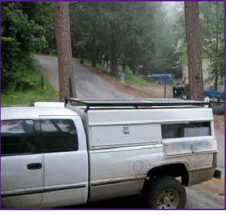
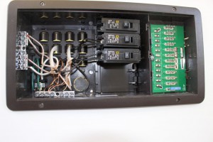
This is a picture showing most of the components for van conversion electrical system.
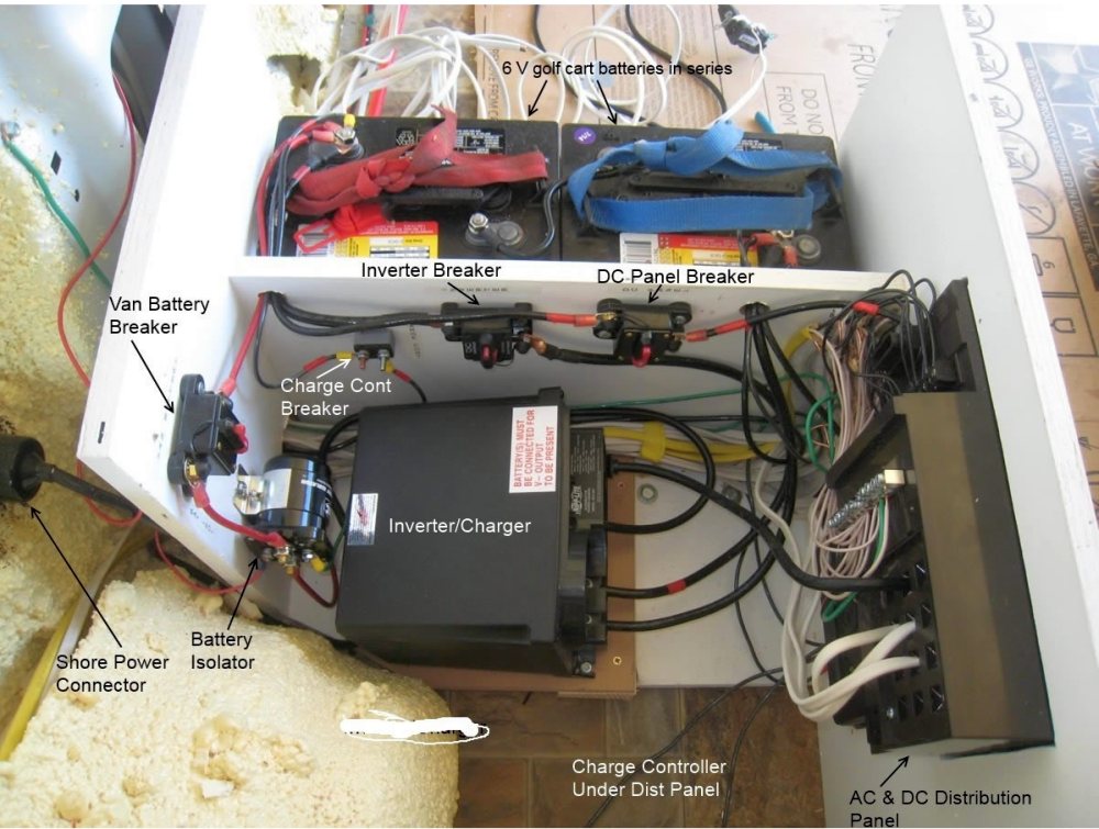
Two systems are described: 1) a simple, small self-contained systems for minimalist camping, and 2) our system, which has more functions and more capacity, but still very buildible.
Overview of an RV Electrical System
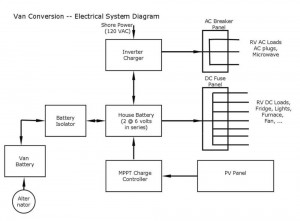
The diagram below shows the electrical system for our conversion. It turns out to be a pretty generic diagram for any camper van electrical system. Your system may not have all of the functions shown — e.g. you might chose not to have solar charging, or not to provide for 120 VAC loads, but the diagram will look about the same except with the parts associated with those functions removed.
If you want to do your own circuit diagram, Digikey Schem-It is a nice, free diagraming tool — wish I had found it before doing the diagrams below 🙂
At the heart of the camper electrical system is the house battery. It provides power for the things you are running in the RV. It needs to be charged up to provide this power, and for the system shown, it can receive charge from three separate sources: 1) the van alternator when the engine is running, 2) the roof mounted solar panel when he sun is shining, and 3) the inverter/charger when plugged in to shore power. Besides charging the battery, the other major function of the electrical system is to distribute power safely to the various RV loads.

A quick over view of what the major components do:
- The House Battery provides electrical energy to power your RV electrical loads.
- The Inverter converts 12 volt DC battery power into 120 volt AC house power to power loads that require house power (eg a microwave). In this system, the Inverter and the Charger are combined into one unit.
- The Charger charges the battery when you are plugged into “shore power” — that is, from 120 volt AC provided by the campground or RV park (or any kind of 120 VAC outlet you can find at your house or a friends house).
- The PV panel and Charge Controller charge the battery from the sun. The Charge Controller regulates the charging voltage and keeps the PV panel from overcharging the battery.
- The Battery Isolator connects the regular van alternator and battery to the house battery only when the van engine is running so that the van can charge the house battery. When the van is not running, it disconnects the van battery from the house battery to insure that RV loads cannot run down the van battery and leave you stuck.
- The AC Breaker Panel distributes the 120 volt AC power from the inverter (or shore power) and distributes it to you 120 volt loads — it includes circuit breakers for each circuit to protect the wiring.
- The DC Fuse Panel distributes 12 volt DC power to all or your RV DC loads (eg lights, fridge,…) — it includes fuses for each circuit to protect the wiring.
The diagrams for most RV’s will look pretty much like this. However, the actual components may be quite different. A small, simple van conversion might have everything combined in something like a single ArkPak box that has everything built into one compact and easy to install box. A larger RV might have half a dozen 100 lb batteries and a components that take up a whole cabinet with lots of point to point wiring. I’ll describe a very simple system and a more complex one (ours) in more detail below.
I don’t discuss generators anywhere because I don’t like them 🙂
Estimating Electrical Demand
Before you can select your components and start building, you need to identify what electrical loads you want to run, how much power they use, and how long you want to run them. You also need to estimate how long you want to be able to camp away from “shore power” — that is, how long your battery has to power the loads.
I’ve put together a separate page on estimating RV electrical demand …
The page will help you decide how large a battery you need, what size Inverter/Charger you need, and what size solar charging system you need (if any).
Choosing Components
This section provides a little advice on picking some of the components for the electrical system. The page on sizing the components for your needs might also be useful.
Our ProMaster camper van conversion has an electrical page that provides a lot of detail on our electrical installation which may be helpful.
Batteries
You will have to choose what type of battery you want to use in your conversion. In any case, you will want to choose a deep cycle battery — this is a battery that is designed to be discharged deeply again and again. Ordinary car batteries are not deep cycle, and will not stand up to service as an RV battery.
Your main choice for house battery will be between two types of lead-acid deep cycle batteries: 1) the conventional flooded lead acid battery, and 2) the AGM (Absorbed Glass Mat) battery. There are a lot of pros and cons between the two, and I’ve put together a separate page that may help with the decision…
Another alternative that is seeing more use lately is the Lithium battery, and the link above includes some information on using Lithium batteries.
For batteries mounted inside the van, the batteries will need to be mounted in a strong box which is bolted through the floor so that the batteries do not become a missile in a crash. If FLA (Flooded Lead Acid) batteries are used, the battery box must be vented to the outside to vent off any Hydrogen produced during charging. There is a potential explosion hazard if it is not vented.
In some cases, batteries are mounted under the van. This link shows an under floor battery mounting.
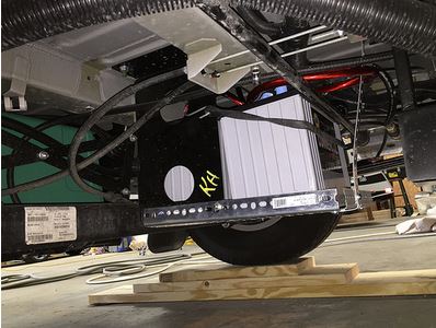
It seems like an AGM battery might be a good choice for this kind of installation as checking water level and adding water is going to be difficult even with the jacking arrangement he has.
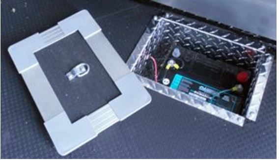
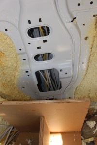
Update: Ran across this recessed battery box on the ProMaster forum. Seems like a good solution in that it frees up some space without exposing the battery to the weather, mud etc of an underbody mount. It also provides nice easy access to the battery from above. Not sure about other vans, but on the ProMaster, there are only a limited number of places that this box will fit, so some early planning is in order if you want to use it.
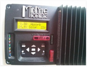
You will want to have a way to monitor (at least roughly) the charge status of the house batteries. An easy way to include a small digital volt meter that you can check. The voltage of a lead acid battery at rest depends on its state of charge, so you can get a rough idea what the state of charge is by checking the voltage — its pretty rough, but much better than nothing. Another approach is to use a charge monitoring system (e.g. TriMetric) that gives a precise reading on how much is left in the battery at any time.
Inverter/Charger or Power Converter
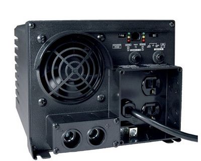
A lot of camper vans these days use a combined inverter and charger unit. When you are hooked up to shore power, this device charges your house battery and supplies 120 VAC power to the gadgets in your RV that require regular household power. When you are away from shore power, the same unit has an inverter which supplies 120 VAC power to the RV from the house battery. This Trip-Lite is one example.
I like this kind of inverter/charger approach because: 1) it eliminates the need for a separate battery charger to charge from shore power, 2) it has 3 stage charging, so its easy on the battery, 3) it automatically switches from the inverter powering AC loads to the shore power when you plug into shore power, so you can hook your AC loads up to the inverter and they will be powered whether you are on shore power or on house battery power.
Update 1/1/2016: One thing I’ve noticed is that pure sine wave inverter/chargers have dropped in price some, so if you plan to run AC loads that might need the pure sine wave output, you might want to upgrade to a pure sine wave inverter — one example is the Xantrex Freedom HFS 2000 Inveter Charger.
The other approach is to use a Power Converter (basically a battery charger and DC power supply). While hooked to shore power, the power converter can charge your house battery and supply 12 volt DC power to your 12 volt RV loads. Best Converter offers some options. It is good to have a true three stage battery charger that can be setup for either AGM or FLA batteries and provides separate stages for bulk, absorb, and float charging — a good charger is probably the main factor in not killing your batteries before their time (which is very common).
Its good to have a way to turn off or disconnect the inverter when it is not in use because it draws some power even when just sitting there doing nothing, and this is an overnight drain on the house batteries.
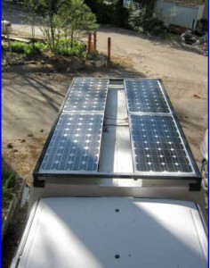
Solar Charging
Solar charging allows you to charge the house battery using photo voltaic panels mounted on the roof (or elsewhere) of the van. The advantages include: 1) being able to charge your house battery without having to run the van engine when you are camping at a spot that does not have shore power, 2) keeping the house batteries healthy and charged when you are at home without having to have the camper plugged into the house, and 3) saving some energy (especially if you are a full timer or do a lot of RVing).
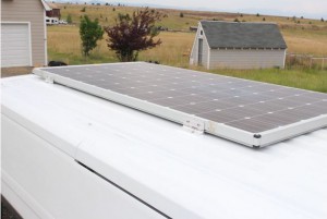
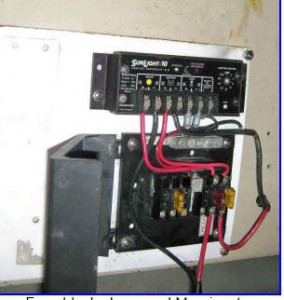
The Solar charging system consists of one or more PV panels and a charge controller. The charge controller goes between the PV panels and the house battery — it increases the efficiency of the solar charging, and (most important) does not allow your PV panel to overcharge (and destroy) your battery.
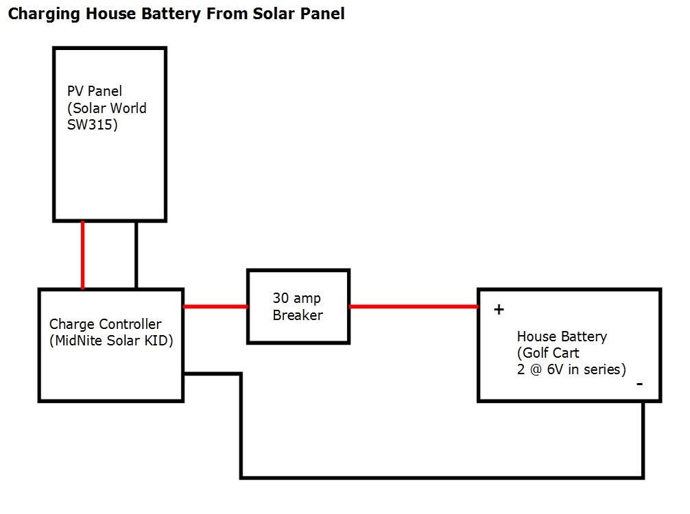
The diagram shows the part of the electrical system diagram that provides solar charging for the house battery on our system.
There are a couple of decisions to make in designing and building a solar charging system, and some tools that are helpful — I’ve done a separate page on solar charging systems here…
Charging from Van
The diagram below shows just the part of the electrical system for charging the house battery from the van charging system.
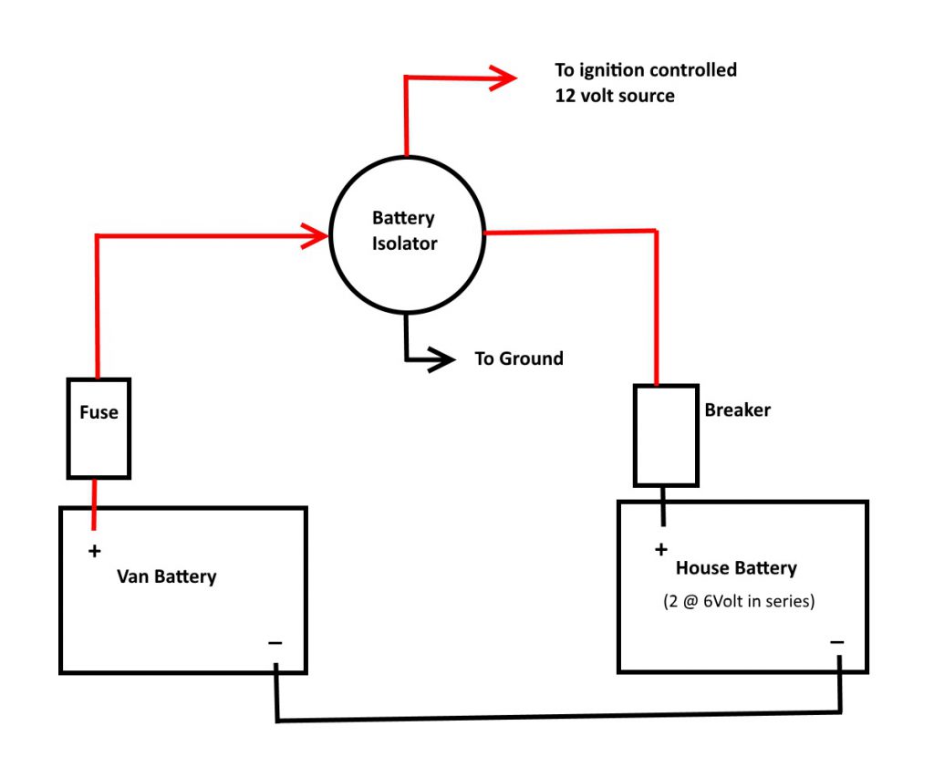
Most systems provide for charging the house battery from the van alternator. This just consists of running a wire from the van battery to the house battery. This wire should be large enough to carry the maximum charging current anticipated, and the wire should be protected by fuses on both ends — that is a fuse in the wire near the van battery and another fuse in the wire near the house battery. Two fuses are required because you have a large source of power at both ends of the wire. In addition, a Battery Isolator is normally used in the wire between the van and house battery. The fuses should be as close to their respective batteries as possible — fuses such as the Mega Fuse allow the fuse to be connected directly to the battery terminal or bus.
Lead acid batteries should not be charged at more than C/10 to C/5 where C is the rated capacity of the battery in amp-hrs. So, for our 220 amp-hr battery the maximum charging current is about 33 amps. We used a 50 amp breaker in the charging line so if the batteries are being charged at too high a rate the breaker would trip and alert us.
The Isolator disconnects the house battery from the van battery except when the engine is running — this keeps you from accidentally discharging the van battery to the point where it cannot start the van. The VSR (Voltage Sensing Relay) is an alternative to the Battery Isolator that works just as well and is easier to hook up. It is also possible to just have a manual battery cutoff switch in place of the Battery Isolator, but you have to remember to turn the switch off and on at appropriate times. Its not such a bad idea to have the manual cutoff switch in addition to the Battery Isolator in that it gives you the ability to disconnect the house battery from the van charging system (say when you are on solar or shore power).
See the sizing page for sizing these components…
Battery Monitoring System
A Battery Monitoring System is an optional gadget that basically tells you accurately how much juice is left in the battery.
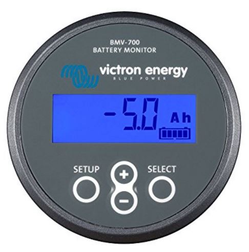
We recently added a Victron battery monitor to our conversion — full details here…
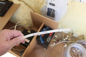
Wiring in the battery monitor requires adding a shunt to negative terminal of the battery, so if you think you may want to install a battery monitor at some point in the future, I would reserve a space for the shunt near the negative terminal of the house battery — the link above shows what the shunt looks like.
Wiring
For the DC circuits on camper vans, many conversions use ordinary Romex house wire. The Romex style wire is readily available, easy to work with, and provides the outer protective plastic cover that helps to protect the wire. The sizing page provides some tools that help you choose what size wire to use. The wiring for our conversion used nearly all of one 250 coil of #13 Romex plus a few feet of #12 Romex.
Some sources advise the use of stranded wire for RV’s in that it is more flexible and better able to take the stresses imposed in the moving vehicle environment. Something to think about, but the solid Romex style wire is widely used.
For a few places where heavier wire was needed, I used THHN stranded wire from Lowes. I used this heavier wire on: the inverter to battery run, the DC panel to battery, and the van to house battery wires. I bought the wire at Lowes — they charge a lot per foot, but they will sell you exactly what you need cut off a large coil.
Each DC circuit must be protected by a fuse or breaker of the appropriate size. A distribution panel of some type will be required to mount the fuses. The panel we used provides both AC and DC distribution in a single fairly compact unit. The number of DC circuits seems to grow and grow as you get into the build, so I would try to get a distribution panel with more circuits than you think you will need. Our panel provides 12 DC circuits, and we are down to having only 2 spares at this point.
For AC circuits, the same Romex wire can be used. Most camper vans don’t have a lot of AC circuits, so wiring tends to be minimal. The AC wiring must, of course, be protected with AC circuit breakers. A distribution panel of some type will be required to mount the master and branch circuit breakers. The panel we used provides both AC and DC distribution in a single fairly compact unit.
Some wiring hints:
- When insulating, think about where you will want to run the wiring and leave space (or do the wiring first)
- Clearly mark both ends of each wire with what load it serves (e.g. galley lights) — this will save a lot of puzzling when you got to hook them up.
- Where wires go through places where they could be abraded, cover with flex conduit.
See the sizing page for wire sizing detials…
Some Example Systems
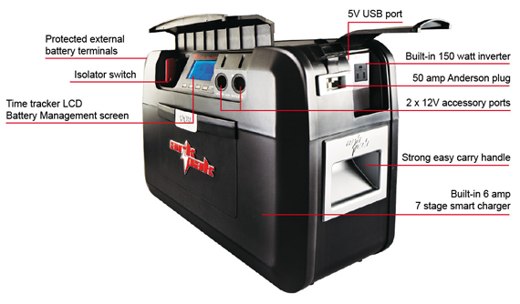
A Really Simple and Portable System
If you just want to do simple camping with a few small loads, this kind of system might be good for you.
It consists of a heavy duty box that holds the battery, and built into the box are:
- A small inverter to for minimal AC loads (maybe a small TV or ?)
- A couple cigar lighter style 12 volt outlets to power
- A built in charger with control panel to show battery status.
- A built in battery isolation switch.
An example of this kind of system is the ArkPak… This one appears to be well made, if a bit pricey, but I’m sure there are other systems out there, or you can build the system yourself using off the shelf components — see below.
Depending on the battery size you pick to go in the box, this kind of system will be able to power: a few LED lights, a radio, a laptop, a fan, and things that plug into a USB port for charging — quite a bit.
It will not give good results for things like: a typical electric RV fridge, any kind of electric resistance cooking, a microwave, an RV air conditioner, a hair dryer, … With these loads, it would not run at all, or would very short battery life.
Some loads that it would be marginal on include an efficient electric fridge (eg one using an efficient Danfoss compressor) — 40 amp-hrs a day, A propane furnace with an efficient blower — about 25 amp-hours a day.
If you used the largest battery it takes (130 amp-hrs), and you discharge the batter to 20%, then you have about 100 amp-hrs available. So, with just the small loads, you might get a couple days out of the battery without charging, but if you had one the larger loads plus regular loads, it would likely need recharging each day.
This is the data on an AGM battery Trojan group 31 AGM battery… This is a 100 amp-hr battery — could not find a 130 ah AGM.
A nice feature of this system is that you can pick the whole thing up and carry it to (say) a tent or outside use. It would also provide a little backup power for power outages a home.
You could buy the individual pieces (battery box, small inverter, sockets, disconnect switch, small charger, and wire) and put something with the same functionality together yourself for substantially less money (see next system), but it is nice to have all of it packaged for you.
Another Simple System
The Yeti 1000 system is another option along the same lines as the ArcPak, but it uses a Lithium battery and provides more more life — it would meet the electrical needs of many van conversions.
In one 42 lb box that measures 10 by 15 by 14 inches, they provide a 1000 watt-hr (83 amp-hr) LI battery, 1500 watt pure sine inverter, PWM solar charge controller, battery monitor system, AC outlets and DC outlets, and USB charger outlets.
It will charge from solar panels, 12 volts DC(eg from the van), and/or AC shore power. It costs about $900 at Costco.
Seems like this might make a nice solution for someone who wants a very simple, all in one box electrical system for a conversion. It could be mounted in such a way that the outlets are directly accessible to plug things into. Or, it could be enclosed and your run a little wiring from its plugs to outlets anywhere in the RV. It could be installed in such a way that it could be removed easily and used outside while camping, or as emergency power for a power outage in your home.
It can be solar charged and is capable of handling as much as 360 watts of solar — more than you will likely need. But, as Matt from the ProMaster Forum points out, charging on shore power is slow as the charger provided is low in capacity — a full charge is going to take overnight (maybe more).
They list the battery type as Li ion NMC, so not the LiFEPO4 used in a lot of RV conversions. They list the life as “hundreds of cycles”, not the thousands of cycle claims you usually see for LI van batteries — maybe they are just being conservative (or realistic) in the life claim. Maybe someone knows how the these two Li chemistries compare?
There is also a larger version called the Yeti 1400, and they also make an lead acid AGM version.
I know all of us that have slogged through the usual RV electrical system component selection, wire sizing, fusing, grounding issues… would never consider such an easy solution — or would we 
Another Simple DIY SystemWith Solar
This is also a nice simple system like the one above, but with quite a bit more capacity and with a large capacity solar array to charge it, and a low cost.
The system components are:
Four 80 watt monocrystalline PV panels for 320 watts total of PV power.
Four 12 volt, 95 amp-hour AGM Batteries.
Two 10 amp charge controllers and fuse blocks.
Assorted cables and wiring.
An inverter will be added to the system when 120 VAC “house” power is needed.
Note that this systems is basically built as two identical and independent systems resulting in quite a bit of capacity — one could just build one of the systems for a total of about $330 in parts including solar charging.
All the details on this system….
A More Complicated System
This is the system we used in our ProMaster camper van conversion. It is the system shown in the diagram near the top of this page.
It uses two 6 volt golf cart batteries for power, providing 220 amp-hrs (175 amp-hrs usable) capacity. It can be charged from three sources: 1) the van alternator, 2) the solar panel on the roof, and 3) the charger that operates from shore power. It supports twelve DC circuits with fuse protection. It has a combination battery charger and inverter — the charger provides battery charging when plugged into shore power, and the inverter provides power for 120VAC loads when shore power is not available. The distribution panel used provides for twelve DC circuits and two AC circuits — just about right for a lot of camper van conversions.


LOTS of detail on this system here…
I saw that you commented on some lithium threads on the PM forum. I’m researching the cold temp charging issues with that system. The self warming Battleborns are +$300 each so wondering about other ways. Do you have simple/safe ideas? I see tank pads that use 4AH with no temp adjustments. My wife uses outdoor pet pads that use only 20W @ 120v. Cats love ’em. Seems like minimal solar could keep up and no danger of overheating batteries in an insulated box. What do you think? I’m going to put one in a cooler with water jugs & see what happens.
https://www.amazon.com/Lectro-Soft-Heated-Pet-Bed/dp/B000ICGJZK/ref=sr_1_6?dchild=1&keywords=Best+Outdoor+Electric+Pet+Heating+Pad&qid=1612479448&sr=8-6
Hi Rob,
I want to first say that what I know about Li batteries would fit in a thimble, so be sure to look further into any of my thoughts carefully before adopting them.
It does seem like some kind of a low wattage heater would do the job — does not seem like it would take much to keep them above freezing.
If you had (say) 0F outside a box that is (say) 2 by 2 by 1ft and insulated with 1 inch polyiso, it would take (16 sqft)(32F – 0F)/(R6) = 85 BTU/hr, or 25 watts.
Another possibility would be to place the fresh water tank and Li batteries inside the same insulated box. The thermal mass of the water and the heat of fusion as it freezes at a constant 32F would be quit resistant to going below 32F. This page has some numbers on how resistant an insulated tank is to freezing: https://www.buildagreenrv.com/prevent-water-system-freezing/
The heater wire shown on this same page might also be used to heat a battery compartment.
One thing you would have to look into is whether an Li battery under heavy load in an insulated box is whether it would overheat the batteries. I guess it depends on the internal resistance of the batteries.
The Li batteries so expensive, that I think I would want to be sure that the battery BMS would protect it from charging when less than 32F just in case your battery heater failed. And, that there was protection to turn off the battery heater if the temperature goes above a certain temperature.
But, bottom line, it does seem like some kind of simple DIY heater should be workable.
Gary
Thank you so much for all the great information. I’m in the conceptualization phase of electrical on a 2019 Transit passenger van. I’ve been reading just enough to get confused about the B to B charger devices like the V tech. Do the B to B chargers handle isolating and charging from both alternator and shore power set up?
thanks
chris
Hi Chris,
I’m not aware of any B to B chargers that charge from shore power. Generally they charge the house batteries from the van alternator/starter battery. Some of them also include a solar charge controller, so they can also charge the house batteries from solar panels.
Most people don’t use a B to B charger. Instead they hook the van alternator/starting battery to the house battery via an isolator. The isolator prevents the van starter battery from being run down as RV loads run down the house batteries.
The advantage of the B to B charger is that it provides full three stage charging with all the right voltages for the house battery. This is a pro, but it also adds cost and complexity to the system, and most people don’t use them.
One case where the B to B might be more advisable is if the house batteries are Lithium — the B to B helps to protect the high cost Li batteries.
Gary
Thank you so much for all the great information, i am about to start some of the electrical in my promaster build but i wondering am i able to put multiple loads under one fuse for DC circuits (like you can with AC circuits).. an example would be like feeding a 12v usb port then jump to the 12v water pump to feed that Thank you so much for your help!
Hi Derek,
As far as I know, its OK to put multiple loads on one fuse as long as the fuse and wiring is able to handle any combination of loads you might have going at the same time.
I think its less common to combine on DC circuits because for a give load in watts, the amperage is higher, but as long as the fuse and wire is rated for the combined loads I don’t see any problems.
I have multiple loads on some of my DC fuses.
Gary
I put in a 70 amp fuse at the van battery and a 60 amp breaker at the house batteries, then plugged in a heat gun and ran the batteries down to 70%. Started up the van and increased rpm some; no problems. Hopefully it will stay that way.
Thanks,
Paul
Thanks. I have the exact same 6V flooded Interstate batteries as you do. I was somewhat conservative with the 50A breaker; it’s 8 gauge wire with about a 9′ run, so a 60A breaker should be fine. I’m going to change that, and look for maybe a 70A fuse at the van battery end. I can’t readily change the wires as they are embedded in the floor insulation.
I never really thought about this issue. So does the van battery accept up to 180A charge? I read somewhere on the PM forum that it does, right after starting the engine. That seems like a lot.
That sounds good.
I actually have a 100 amp fuse on the van battery end of my setup. Its really there to protect against a short of the wire to ground between the two batteries. I once saw a #14 wire blow a 200 amp breaker when I was changing out our circuit breaker panel on our house. The insulation was not even burned.
Thinking I will change out the breaker on the house battery end to 60 amps also just to give a bit more margin.
Please let us know if it works OK.
Gary
Gary, We just returned from our first longer trip, seven days in Eastern Oregon. Only one issue: the 50 amp breaker near the house battery on the van charging circuit (from van battery through isolator) kept tripping, after the house battery had bee run down into the 80-70% range from microwave use.
Actually, the 50 A fuse on the other end, at the van battery, had already popped on our first shorter trip, and I removed it because I didn’t have another.
So it appears that the house batteries are drawing more than 50A, and of course the van alternator, rated at 180A, can supply much more than that.
How is the charging draw supposed to be kept at less than 50A with a 180A alternator? Am I missing something? And what do I do about these popping fuses and breakers. It was a good thing we had a solar panel. I did reset the breaker once I figured out what was going on, and sometimes it held, other times not. I suspect it popped when the batteries were more drawn down, but I’d have to test that for sure.
Hi Paul,
Two things to think about. The batteries may be OK with a charging current in excess of 50 amps — see if the manufacturer can give help on this. If they are, then replace the 50 amp with something larger. But, try not to put in a breaker that is greater than the ampacity rating of the wire. You should also replace the fuse at the van battery end — you could use a larger fuse here as it just protects the wire against shorts to ground.
If your batteries are AGMs, its quite possible that they can be charged at a higher rate without damage.
If you find the batteries should not be charged at more than the 50 amps, then you could try adding some more resistance in the line to the house battery — this would drop the voltage a bit and therefore the charge rate. Not sure what the best way to do this is.
Gary
Hey Mark,
I appreciate all the great information you’ve provided! As I am very much a novice to electrical systems, I ponied up the cash and purchased a Yeti 1400 for my small trailer camper. I am now having trouble determining how to wire this into my DC fuse box to provide power for my internal systems (furnace fan, LED lights, fans). Any detail you can provide or resources you can point me to would be greatly appreciated. Thank you!
Andrew
Hi, I was wondering what your advice would be for grounding the battery? Is it okay to attach it to the frame of the van? we have a 2005 sprinter.
Thank you for the help!
Hi Stephanie,
My take would be that it depends on how you hook up your DC loads to the house battery. If you run positive and negative wires to each DC load (ie two wires to each DC load), then the house battery to frame ground will not be carrying much current and is more of a safety ground. This is what I did, and my ground wire from house battery to van frame is something like a #10 (ie not that heavy).
If, on the other hand, you only run a positive wire to each DC load and ground each DC load to the frame for the return current path, then the ground wire from house battery to frame is carrying the return current for the sum of all the DC loads you have running, and it should be a heavy wire sized to carry this current.
I like the first scheme in that over time grounds tend to corrode and make for electrical problems that can be hard to find. But, the 2nd scheme is OK as well as long as you are careful to do good grounds.
Hope that makes sense?
Gary
Will you please give me advice on my system?
I am converting a Ford E450 diesel with dual alternators with no electrical modifications. I am not sure how the Dual alternator system works. My problem is that the van battery breaker between the isolator and the house battery trips in the first few minutes of driving the van. It is fine at idle, but trips after a minute or so at 1500 rpm. I have four 100 amp 12 volt batteries and am using a 100 amp circuit breaker.
Hi Mark,
My knowledge here is pretty thin, but here are a couple thoughts and questions:
– Are your house batteries AGM or flooded?
(this effects the max charge rate)
– It would be good to get the voltage at the house battery under the conditions around 1500 RPM when the breaker goes. And, the charging current to the house batteries at the same time. If you have a battery monitoring system like a Victron or TriMetric, it would give you both of these.
eg: https://www.amazon.com/Victron-BMV-700-Battery-Monitor/dp/B00MJ9TAN8/ref=sr_1_3?ie=UTF8&qid=1521151060&sr=8-3&keywords=victron+battery+monitor&dpID=51mfuHsG-kL&preST=_SX300_QL70_&dpSrc=srch
Or, a clamp on meter that measures DC current. This is a cheap one that looks like it would work: https://www.amazon.com/Tacklife-Multimeter-Auto-ranging-Voltmeter-Resistance/dp/B01N014USE/ref=sr_1_2_sspa?ie=UTF8&qid=1521152006&sr=8-2-spons&keywords=dc+clamp+amp+meter&psc=1
Just make sure that the clamp meter reads DC and AC amps as some of them only do AC amps.
So, just from the fact that the breaker opens indicates that the charging current is 100 amps, or probably a bit more (or the breaker is defective). For 400 amp-hrs of batteries, this is a charge rate of 25% of the 20 hour amp-hr capacity of the batteries. This is too high for FLA batteries and is higher than a lot of AGM battery manufacturers recommend.
I would contact the manufacturer of your house batteries and find out what they recommend for maximum charging current — that is, a charging current above which the batteries might out gas too much or have shortened life.
If it turns out that the charging current provided by the 2 alternator system is too high for your house batteries, then you would want to work out a way to lower it. One way would be to add some resistance to the wire from the alternator to the house batteries.
For example, if you wanted to drop the charging voltage at the house battery by 0.5 volts at 100 amps charging current, you would want to add a resistance of (V) / (A) = (0.5 volt) / (100 amps) = 0.005 ohm. About 12 ft of #6 wire would be pretty close, and it would handle the 100 amp current OK.
If it turns out that he battery manufacturer is OK with a higher charging current than 100 amps, then you could just try using a larger breaker.
I’m not at all familiar with dual alternator systems, but for a single alternator system, a 100 amps of charging current would be very high — even 200 amp alternators don’t typically put out this kind of charging current to a house battery.
Gary
Hello Gary. Thank you for your complete response. It helped me to take specific action on my problem. Here is what I think is happening:
First, I have four 100-amp AGM batteries. The manufacturer is not very forthcoming about the maximum charge amperage, but indicates on their web site that 100 amps on my system should be fine.
As I said, the engine has two alternators. The first charges at from 59 to 69 amps depending on the engine speed and electrical draw. The second alternator sometimes kicks in and the total amperage charge jumps to between 145 and 150.
The trigger for the second alternator kicking in seems to fall into three categories: (1) for less than a second within a minute after every initial start of the engine; (2) when the batteries are at less than 8 volts; and (3) when I place a strong draw in the batteries through the house system, like starting the microwave.
I believe that each alternator is capable of putting out 75 amps. I never see just 75 amps because when the draw approaches that, the second alternator kicks in and it jumps to the 145-150 range. It looks like a continuous charge on not-very-low batteries (by far and away the most likely situation) is at about 55 amps – which should be just fine for my system. When the batteries fall below 8 volts, it charges at 145-150 amps for less than 5 minutes, then drops back to the 59-69 range continuously.
Questions:
1) Do you think the dual-alternator 150 amp charge for a few minutes when they are below 8 volts is going to harm my batteries? The manufacturer would not commit either way. I think this will be an unusual situation: It took me quite a few days to get them to drop from 11 volts (where the inverter no longer works) to 8.
2) Since the dual-alternator 150 amp charge under heavy load (i.e. with the microwave running) does not seem to be going to the batteries, can I just be thankful for it and ignore it?
3) Given the dual nature of the system, can you recommend a protection strategy? Like putting in a 200 amp breaker? This does not seem to provide much protection at all. Or maybe putting in a breaker on each alternator over on the engine side of things. This
seems over-kill, and I’m not sure just how to go about it.
Thank you again for your input and assistance,
Mark
Hi Mark,
8 volts is really really low for any kind of lead acid battery, and I think you need to take steps to keep the batteries from getting this low — I believe that it will shorten their life significantly.
You might want to consider installing a battery monitoring system — this is one example: https://www.amazon.com/Victron-BMV-700-Battery-Monitor/dp/B00MJ9TAN8/ref=sr_1_3?ie=UTF8&qid=1522810257&sr=8-3&keywords=victron+battery+monitor&dpID=51mfuHsG-kL&preST=_SX300_QL70_&dpSrc=srch
It will monitor current into and out of the battery and tell you the state of charge. A lot of people try to not go below 50% state of charge, but I think getting down to 20% once in a while its OK. Going below 20% will definitely shorten life.
I’d guess that if you keep above 20%, you won’t see the 150 amp charging rate that you see with the 8 volts.
I agree that if the charging current goes up when you have a heavy load like the microwave going in addition to the regular charging that the higher current is probably OK.
I don’t really know enough about the two alternator setup to suggest a protection scheme.
I guess one thing to keep in mind is that the main thing the breakers are there to do is to protect the wiring, so be sure to set the breaker size that is no larger than the max current carring capacity of the wire. The BlueSea Circuit Wizard is a good calculator to use to set your wire sizes.
Gary
One or two more things: The run from the van battery to the house batteries is going to be more like 12-13 feet. Would a #8 cable still likely be big enough, for those two 6 v batteries. I’d limit the charge like you do with a fuse.
I was thinking about a Yeti, but the very slow charge time was a turn-off. If the weather is cloudy, I’d like to be able to get a decent charge on the batteries in a couple of hours, not an all-day drive.
I was a bit intimidated at first, but having re-read your electrical chapter a couple of times, it’s starting to feel much less intimidating. And I like the flexibility of having one’s own system, or being able to fix a single component instead of dealing with a broken Yeti.
Hi again 🙂
I do think you should go to heavier wire for that longer run. Using the BlueSea Circuit Wizard and 24 ft round trip wire length and 2% voltage drop and 40 amp charging current, it comes out with AWG 4. The heavier gage is just to keep the voltage drop down on the longer run.
I’d also consider putting a manual switch in this run if you have a good place to put it. This would let you disconnect the van battery from the house battery in cases where the solar charging is doing the job (probably most of the time).
I agree on the Yeti — its a pain that the charger is so slow.
I think you will be happier doing your own system, and, as you say, the wiring is really pretty simple. I think the Yeti is a good choice for people who just don’t want to mess with wiring at all.
Keep us posted on how it goes.
Gary
I’m going to pattern my electrical system on your, with a few changes. I am still planning to use an Energy Star rated 4.4 cf Magic Chef 120v fridge (228 kWh) that I will super-insulate. But I assume I’ll want a 2000W inverter/charger. I’m looking at the Xantrex Freedom true sine. Any thoughts on it or any others I might want to look at?
I also have a cheap little microwave with just a mechanical timer that a tenant left behind, rated at 600 or 700W. probbaly won’t use it much, but it might come in handy.
And since I decided to have hot water, I’m looking at a 4 gal Isotemp, which would of course primarily be heated by the van engine. it does have a 700W AC element, but I would expect to use it rarely, as we tend to not stay in one place very long.
I will of course have to turn the fridge off before using the microwave or water heater.
I’m planning on the same 6V batteries as yours. And a similar solar panel. My loads are probably going to be somewhat higher than yours, but I think it’s doable.
Any thoughts? I suppose if I find that I don’t have enough battery capacity I could always add a single 12v. I will have enough room, as my van is longer. Or does that not work so well?
Hi,
I would like to hear how the Magic Chef works out — I think it may do well, especially with the extra insulation.
Without the extra insulation, the 228 KWH per year would be about 0.62 KWH pe day, or about 620 watt-hr / 12 volts = 52 amp-hrs per day maybe a bit more with the inverter inefficiency. But, the extra insulaition should help.
Could not find how much power it pulls in watts when on, but I’d guess not an awful lot — probably less than 100 watts?
Some fridges these days have the condenser coil basically bonded to one of the fridge walls — if this is the case on yours, you want to be careful not to insulate over this area as it would greatly reduce efficiency of the fridge.
I think that a 2000 watt inverter charger should be plenty for your loads. Agree that pure sine wave is the way to go these days.
Microwaves are rated on output power to the food, and input power from the outlet will be more — maybe 900 watts in for your 700 watt microwave?
About the only thing that has kept us from adding a small microwave is a place to put it, so, I guess, plan for it from the start is good.
I don’t have any experience with Isotemp, but we did have a hot water tank on an earlier RV that got its heat from the engine coolant via a heat exchanger and I liked it a lot. It had no electrical backup, but rarely left us without hot water.
I do think the same batteries we used would be OK — especially if you usually move each day. We rarely see our batteries below 80% SOC, so, for our loads there is quite a bit of margin.
Gary
Hi Gary,
We’re in the midst of converting our 159 wb promaster and getting to the stage where we’re looking at electrical. Neither of us have much electrical experience at all. Our needs will be powering a fridge, lights, water pump, and phone/computer charging. We’ll have solar panels and would like the ability to be off-grid for a few days at a time. Do you think a yeti system would be sufficient for our needs?
Thanks!
Hi Abby,
The Yeti 1000 battery has a capacity of about 98 amp-hrs, and since its a Lithium battery you can use nearly all of this capacity without degrading the battery.
On your loads, the fridge is the big one — ours uses about 40 amp-hrs per day — details here: https://www.buildagreenrv.com/design-and-build-information-for-camper-vans/installing-galley/measuring-refrigerator-electricity-use/
The water pump, lights and charging probably add about 10 more amp-hrs per day.
So, without the solar (or on cloudy days) and with no charging from the van engine, you could do one night fine, but 2 nights is getting pretty marginal.
You might be able to find a more efficient fridge, but the one we have that uses 40 amp-hrs a day is already pretty good. You must avoid an inefficient fridge — there are some out there that would drain the battery to nothing in a day.
Some of the Engel chest fridges are reported to be quite efficient.
If you had (say) 200 watts of solar — maybe 2 100 watt panels that are compatible with the Yeti? On a sunny day, you would get near 100 amp-hrs a day, which would take care of all your needs.
It would be better to charge your phones/computers with 12 volt DC chargers that plug into the Yeti 12 volt outlets than using an AC charger from an efficiency point of view.
The Yeti is a bit limited on the maximum DC current you can draw from it, but I think it would be OK for the loads you have.
The Yeti has some limits on how it can be recharged either from AC (like shore power) — they quote a time of 18 hours to recharge the battery from an AC outlet. Slow, but if you are plugged into shore power overnight the long charge time might not matter.
For charging from the van, I think you could use the same DC input that they use for the solar panels, but charging would likely be pretty slow and van run time might be longer than you like.
Think about any other loads you might want to add (eg a furnace with electric blower could add another 20 amp-hrs a full day in cold weather).
Overall, I think it could work OK with your loads. You would want to monitor your usage and be prepared to scrimp a bit in cloudy weather.
A lot of people with fairly modest loads (like you and me) have found that 200 watts of solar keeps the battery up well enough not to have to use any other charging source.
All that said, I’ve never used a Yeti, so I could be missing something. I do like them.
Another thought would be to use the Yeti, which would get you an electrical system right out of the box. If at some time later you decide you want a bigger, higher capacity, fancier system, you could retire the Yeti to emergency power for your house and build an electrical system for your van. It would help in this approach to have a space identified where the bigger system might go, and a way to run wires to your loads.
I think the Yeti is a good way to get your conversion on the road faster and avoid getting stalled on the electrical stuff.
As you likely know, Costco has the Yeti 1000 for $1K.
Just noticed that the Goal Zero website is offering some “open box” deals on the Yeti 1000 and 1400 that look pretty good. If you wanted some extra margin, the 1400 might be a way to go.
If you go with the Yeti, would really like to get a report from you on how it works out.
Gary
Thanks so much for this material! It’s all very helpful. Can you help me out with a suggestion or two? I’m thinking of converting a 14′ cargo trailer into a simple camper, the purpose of which is simply to have a pleasant place to sleep at night between full days of outdoor fun. During the day there would be minimal power needs: some LED lighting, maybe a coffee maker (6-8 amps but only for a few minutes). But on warm, muggy nights–I live in the South–I’m going to run a portable AC unit that draws 9 amps. It will probably cycle off and on throughout the night.
Here’s the question: what’s the best way to meet those power needs? Clearly I’ll need to run a generator at night. What if I used the Yeti (or similar product) as the power source for lights and a couple of internal electric outlets? At night, would I then plug the AC into the Yeti and the Yeti into the generator? Would that give me good results, or should I consider another approach?
Hi,
For the day loads, I think the Yeti would be fine and easy to do.
If you plan to have a gas cooktop, you might consider just doing the coffee on it as this would be your major electrical load.
I’m not a fan of generators, but for running the AC at night the generator might be the way to go. Maybe something quiet and efficient like the Honda inverter generators. If you camp in campgrounds, just be aware that generators are less and less popular and sometimes not allowed or relegated to limited areas.
There have been some who have tried small and efficient AC units along with quite a bit of solar and and big battery bank. Good insulation is a key to making this work, and limiting the area that is air conditioned also helps. But, it may mean putting more into batteries and solar than you want to do.
I would include a roof fan (like the Fantastic or Maxair) along with window or other intakes for air for those times when its warm, but where you can get by without the AC as long as you have good ventilation. These fans make a big difference in comfort for warm but not brutally hot nights (and days).
Gary
Gary, many thanks for the helpful suggestions!
All the best,
Burke
Hi,
Your site is very helpful thank you. I just beginning a conversion in à Promaster and I want to know were did you pass the wire to go to the van battery. In mine there is some in passenger side pillar. I want to use the same “route”. Is it difficult to remove the plastic garniture on the pillar. Is the wire pass with facility?
Sorry for my english, I’m from Quebec in Canada.
Thank you another time for all the information you leave in your site it’s very generous.
Nicolas
Hi Nicolas,
I’m away from the van right now and I don’t remember exactly how I ran that wire.
I’ll take a look when we get back, but will be about a week.
I do recall that part of the run goes under the drivers seat because I put that part inside conduit. I think the rest probably runs through the back of the galley cabinet that is just behind the drivers seat.
Gary
Thank you for all this excellent information. You are a life saver!!! I am wondering which set up would be best for a 26 foot airstream. We will be living in it full time. Thank you!
Hi Carrie,
It really depends a lot of what kind of electrical loads you plan to run.
If you can provide a list of the electrical stuff you plan to use and how much you plan to use it , I can give you an idea how big a system you might want.
Also good to know if you plan to use mostly places where shore power is available, or if you want go “boondocking” and for how many days you want to be able to go without shore power or driving to recharge the battery. And, if you plan to have solar.
If you can minimize your electrical loads, it does make the electrical system smaller and simpler.
Gary
Excuse my ignorance but why two six volt instead of one twelve volt battery
Hi,
Nothing wrong with using a big 12 volt battery, but it would likely weigh 120+ lbs and be hard to handle.
The 6 volt golf cart batteries are cheap and easy to find because they are so commonly used. In golf carts there are usually 6 or 8 of them hooked in series for 36 or 48 volts.
Gary
as a Nissan Leaf owner, one thing I think would go well with RVing is electric regenerative braking, with the motor(s) proving uphill / acceleration assist too.
The Promaster’s rear axle is a an interesting place to put the motor(s) . . . AWD plus a lot more benefits.
weird how the industry is asleep on this.
That would be a nice capability — lots of times when a limited amount of AWD would be a real benefit.
Gary
If I used your set up, but added a few extra batteries to store more power, would anything else have to be changed in the system?
Hi Nick,
The charging current from the van alternator/battery to the house battery would likely go up some with more house battery, so you would want to check the gauge on those wires.
You might want somewhat more solar charging so the larger pack would not take too long to charge.
I can’t think of anything else that would want to change.
Gary
I’m not clear how much room is needed for converter/charger ventilation? Most look enclosed, but there is a fan, suggesting more is needed?
Hi Mike,
Good question — I don’t know.
I did not provide any kind of forced ventilation for my inverter/charger. I think that it does have an internal fan. It is in the under bed cabinet, so it has a few cubic feet of air space, but no vents. Its never shown any sign of not staying cool enough or shutting down due to overheating. We don’t use the inverter much at all and never (so far) for anything near its capacity, but the charger does sometimes operate near its rating.
I guess that it would not be a big deal to have an inlet and outlet vent for the cabinet the converter is in, and to have a small fan in one of the vents that is triggered by a simple air temperature switch (called a thermal snap disk switch — about $10).
Gary
Thanks for the quick response! I guess it’s not critical, but I’ll try to create opportunity for air flow with some form of venting to keep things cool.
I can’t seem to find any info about the 30/50 amp breakers that you show in your diagrams. I can find ones that are breakers only, but not with a built-in on/off switch. This seems like a very logical thing to have, and I would hate to have to wire in bot a breaker AND a switch. Can you please give me a part number or some other way for me to find out what device you used?
Thanks!
S~
Hi Steve,
This link is not to the same brand I used, but similar:
http://www.amazon.com/Audio-Inline-Circuit-Breaker-Protection/dp/B00FNUI3PQ/ref=sr_1_12?ie=UTF8&qid=1449883948&sr=8-12&keywords=automotive+circuit+breaker
Also got some of them at the local auto parts store.
A 30 amp may be a problem — not sure if they make this style of breaker in that low a version.
One place I found pretty good for getting hard to find electrical components is DelCity: http://www.delcity.net/
Gary